High-current electrical coil construction

a high-current, electrical coil technology, applied in the direction of transformer/inductance details, basic electric elements, electric apparatus, etc., can solve the problems of increasing the weight and size of the coil, increasing the difficulty and force required in winding the coil, and increasing the cost of production of conventional coils, etc., to achieve the effect of high current-carrying capacity

Inactive Publication Date: 2007-07-24
TDK LAMBDA CORP
View PDF4 Cites 58 Cited by
  • Summary
  • Abstract
  • Description
  • Claims
  • Application Information

AI Technical Summary

Benefits of technology

[0003]An object of the present invention is to provide an electrical coil of high current-carrying capacity having advantages in the above respects.

Problems solved by technology

However, as the current-carrying capacity of the coil increases, the cross-sectional area of the wire or strip must be correspondingly increased, which not only increases the weight and size of the coil, but also increases the difficulty and force required in winding the coil.
Such conventional coils, therefore, are not only heavy and bulky, but also are expensive to produce.

Method used


Image

  • High-current electrical coil construction
  • High-current electrical coil construction
  • High-current electrical coil construction

Examples


Embodiment Construction

The 1.5 Turn Coil of FIGS. 1–3

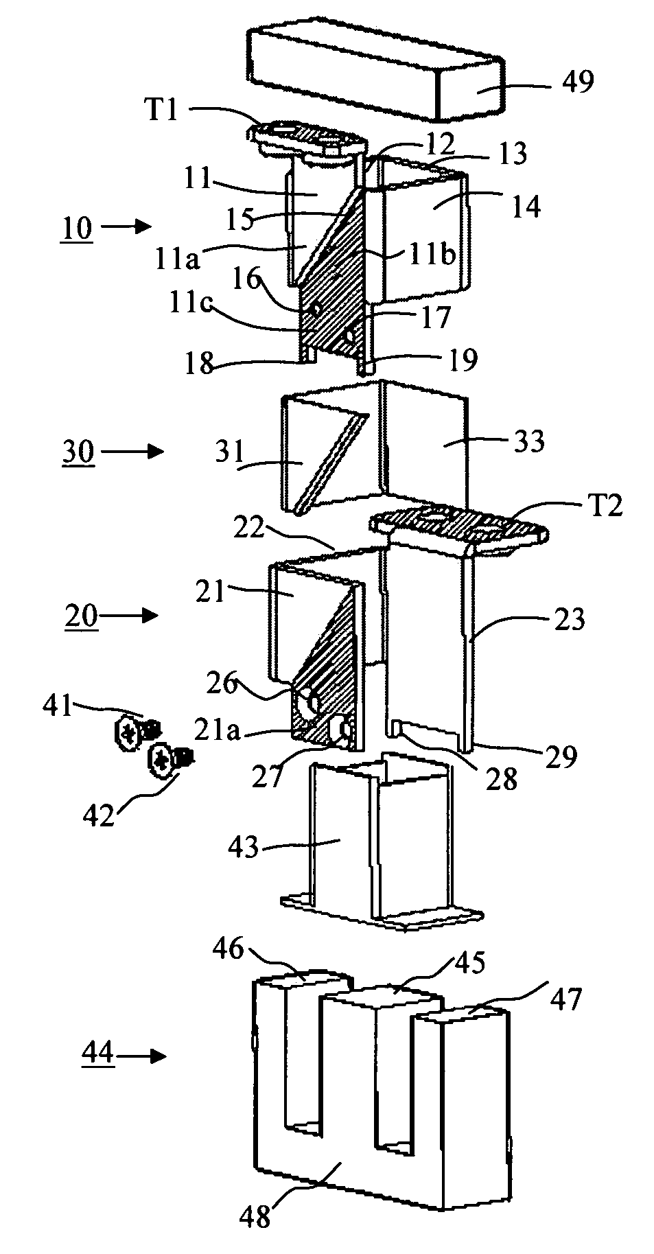
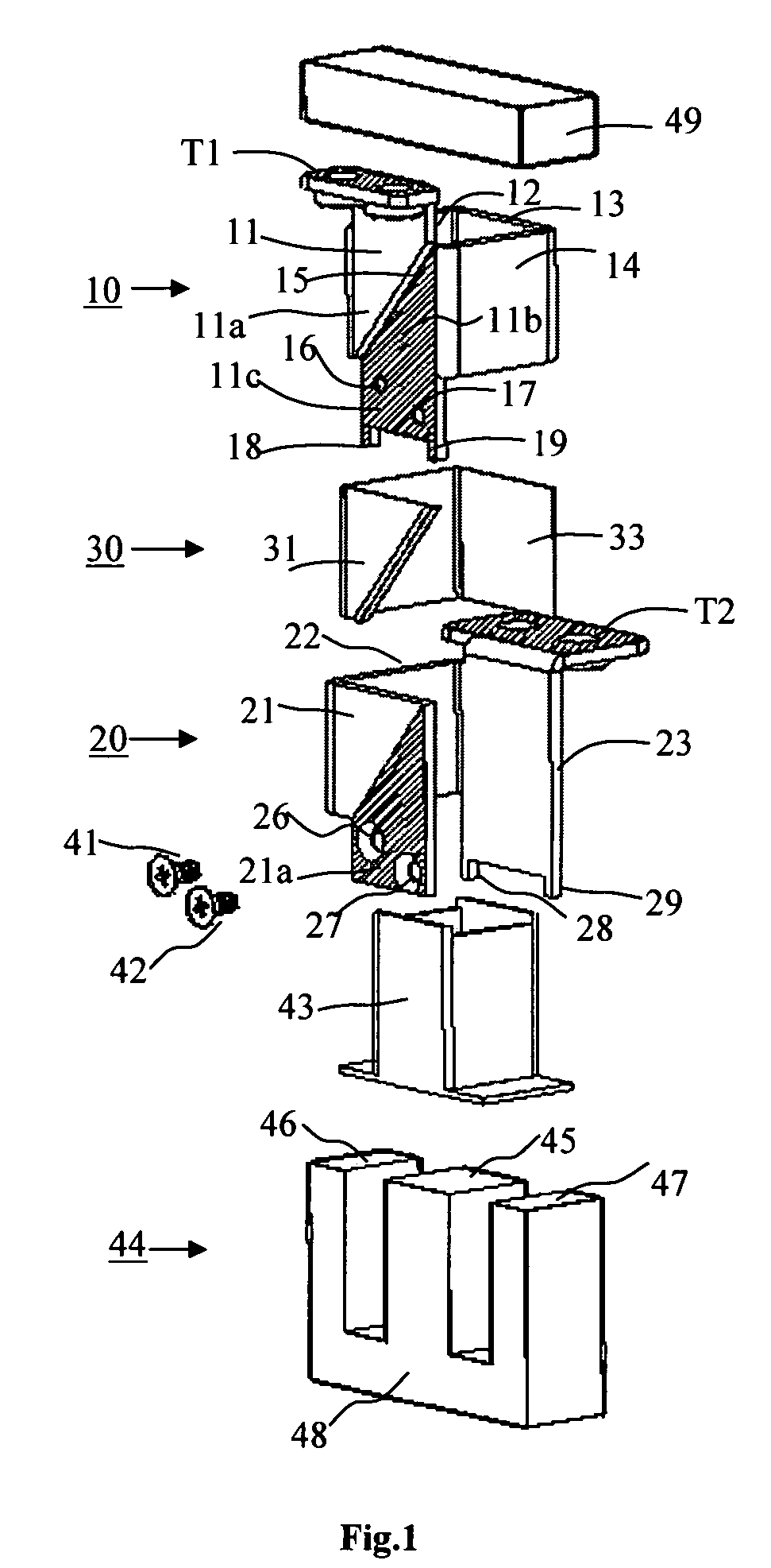
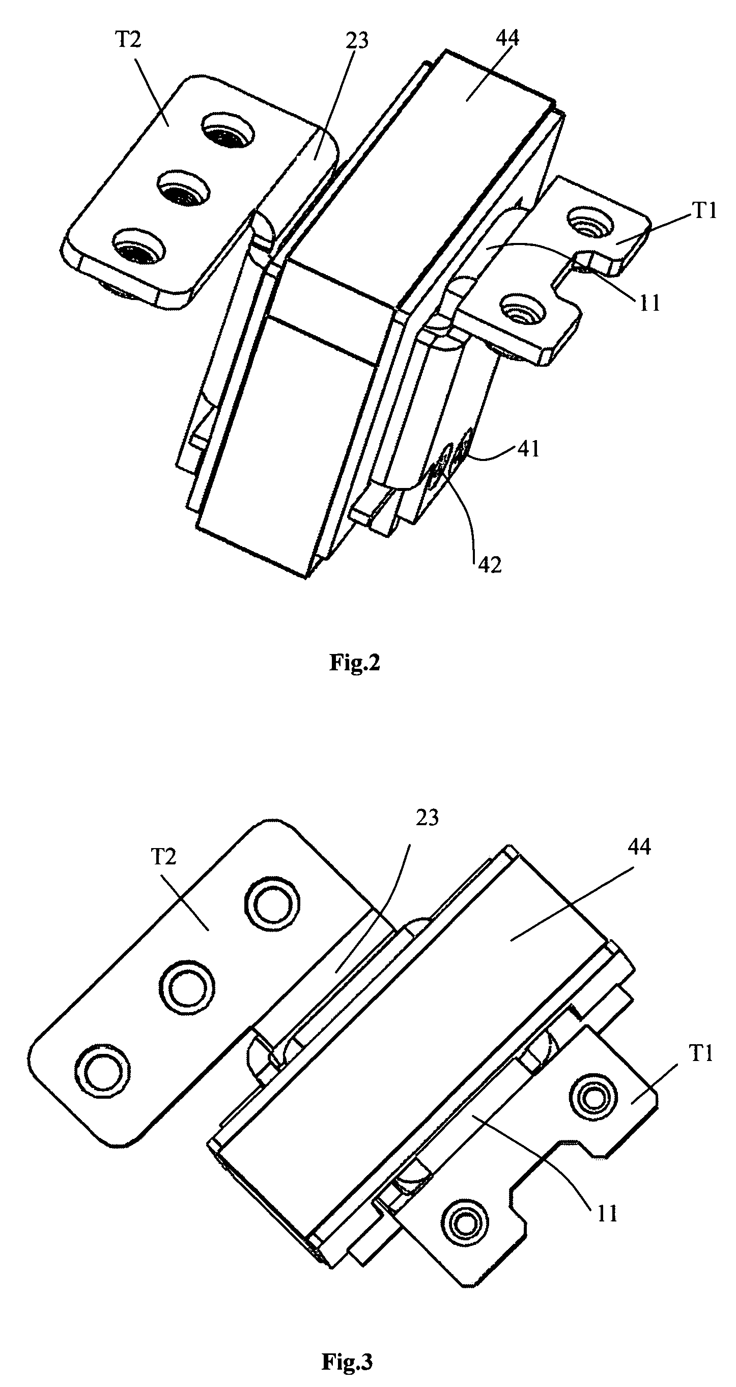
[0019]FIGS. 1–3 illustrate a high-current electrical coil of 1.5 turns constructed in accordance with the present invention. In this case, there are but two flat, electrically-conductive strips, designated 10 and 20 respectively, bent to define together the 1.5 turn coil. The two electrically-conductive strips 10, 20 are disposed coaxially, extend longitudinally, and are spaced radially from each other with respect to the longitudinal axis of the produced coil. In this example, the coil is of polygonal configuration, more particularly of a square configuration, constituted of four equal sides.

[0020]Thus, electrically-conductive strip 10 is bent to define a square-shaped complete turn, including the four sides 11, 12, 13 and 14, respectively. Side 11 is formed with a diagonally-extending gap 15 which divides that side into two conductive sections 11a, 11b on opposite sides of the gap, such that section 11a of side 11, side 12, side 13, side 14, and secti...


PUM

PropertyMeasurementUnit
electrically-conductiveaaaaaaaaaa
electrically-conductive aaaaaaaaaa
electrical continuityaaaaaaaaaa

Abstract

A high-current electrical coil includes a plurality of flat, electrically-conductive strips bent to define together a coil in which the electrically-conductive strips are disposed coaxially and extend longitudinally with respect to the longitudinal axis of the coil. Each of the electrically-conductive strips is bent to define at least a part of a turn of the coil. One electrically-conductive strip has an outer end carrying a first connector terminal for the coil and projecting outwardly of the coil; and another electrically-conductive strip has an outer end carrying a second connector terminal for the coil and projecting outwardly of the coil. Each of the electrically-conductive strips includes inner ends in electrical continuity with each other, and intermediate portions electrically-insulated from each other such that the plurality of electrically-conductive strips together define a coil exceeding one turn between the first and second connector terminals.

Description

FIELD AND BACKGROUND OF THE INVENTION[0001]The present invention relate to electrical coils, and particularly to electrical coils constructed so as to have a high-current capacity for use in power equipment, such as inductors, transformers and the like.[0002]Electrical coils are conventionally made by winding insulated wire or flat strips into coils of the desired number of turns. However, as the current-carrying capacity of the coil increases, the cross-sectional area of the wire or strip must be correspondingly increased, which not only increases the weight and size of the coil, but also increases the difficulty and force required in winding the coil. Such conventional coils, therefore, are not only heavy and bulky, but also are expensive to produce.OBJECT AND BRIEF SUMMARY OF THE PRESENT INVENTION[0003]An object of the present invention is to provide an electrical coil of high current-carrying capacity having advantages in the above respects.[0004]According to one aspect of the p...

Claims


Application Information

Patent Timeline
Patent Type & Authority Patents(United States)
IPC IPC(8): H01F27/28
CPCH01F27/2847H01F27/2852H01F27/325
Inventor PODLISK, ILIARUCAREANU, GEORGE
Owner TDK LAMBDA CORP
Why Eureka
Try Eureka