Method for reducing the out-of-band emission in AM transmitters for digital transmission

a technology of am transmitters and digital transmission, applied in the field of am (amplitude modulation) broadcast transmitters, can solve the problems of unwanted emissions and different output signals, and achieve the effect of reducing unwanted emissions and reducing out-of-band emissions

Active Publication Date: 2007-07-24
DEUTSCHE TELEKOM AG
View PDF16 Cites 9 Cited by
  • Summary
  • Abstract
  • Description
  • Claims
  • Application Information

AI Technical Summary

Benefits of technology

[0025]Influencing the digital modulation signal in the transmitter and its effect on the OOB gradient for reducing the unwanted emissions are an object of the present invention.
[0026]The present invention provides a method for reducing out-of-band emission in an AM transmitter for digital transmission. The method includes: generating, from a digital modulation signal, an amplitude signal and a phase-modulated radio frequency signal configured to control the A

Problems solved by technology

Rather, the output signal is different because of the non-linear distortions occurring during the modulation process and the unw

Method used


Image

  • Method for reducing the out-of-band emission in AM transmitters for digital transmission
  • Method for reducing the out-of-band emission in AM transmitters for digital transmission
  • Method for reducing the out-of-band emission in AM transmitters for digital transmission

Examples


example 1

Modification of an OFDM Signal

[0044]OFDM signals have a fairly rectangular spectrum but feature a noise-like character in the time domain, namely both for the 1-component and for the Q-component of the time signal. This is a result of the occurrence of the interference of many subchannels which are independent of each other.

[0045]If, in the case of OFDM signal, a certain degradation is accepted, that is, a slight increase of the bit error rate for a given signal-to-noise ratio, then it is possible to “bore a hole” in the vector diagram.

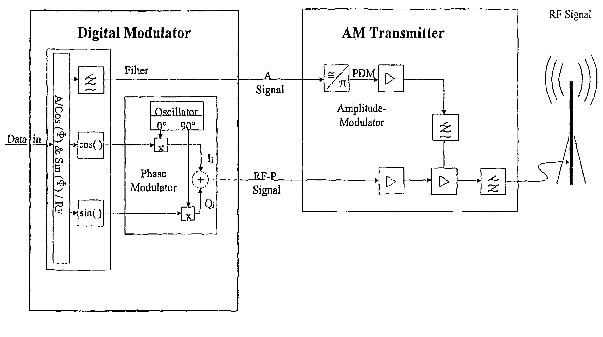
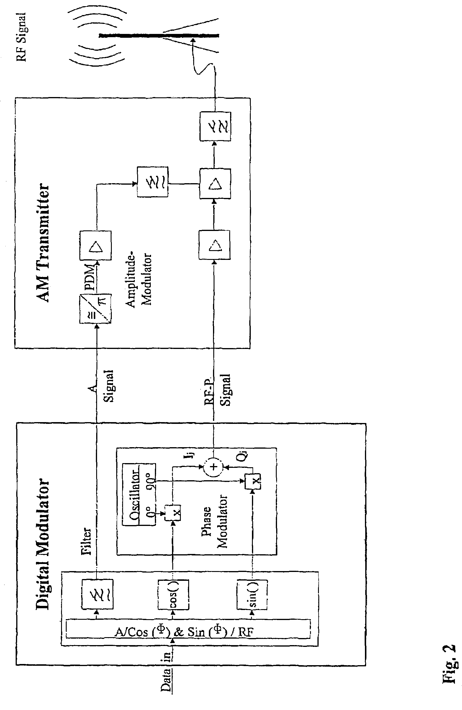
[0046]To this end, it is required to modify the I(t) and Q(t) components of the OFDM baseband signals. Only after this can the I / Q A / RF-P conversion and the transposition to the transmitter frequency be carried out.

[0047]The I(t) and Q(t) baseband signals are AC voltages and therefore each of them has zero crossings. The critical case, in which the 0 / 0 point is approximated or touched in the vector diagram, occurs when I(t) and Q(t) both have a zero c...

example 2

Modification of a BPSK Test Sequence

[0058]To measure the radio channel and also to synchronize the receiver, it is possible to use a BPSK (Binary Phase Shift Keying—pseudo random or CAZAC) test sequence. In this context, the characteristics of the test sequence are to be determined such that no unacceptably high unwanted emissions are generated.

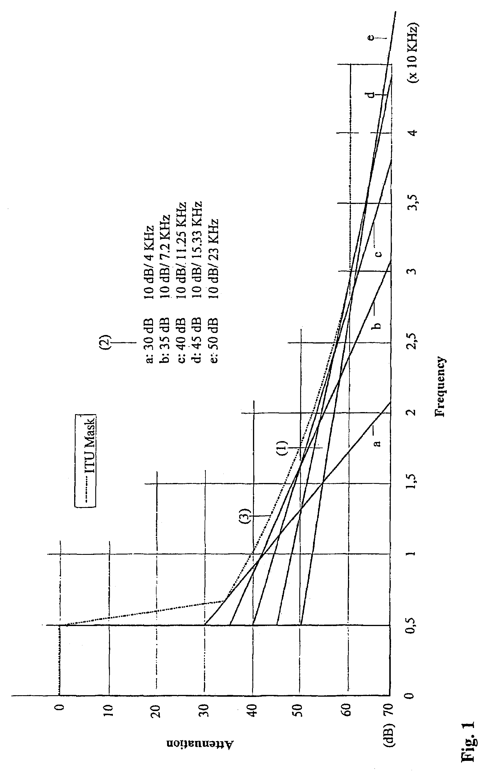
[0059]A non-modified BPSK test sequence has frequent changes in sign. During the Cartesian polar transformation, therefore, sharp peaks with zero contact or almost zero contact occur in the A-signal as well as jumps by pi in the phase. Both characteristics result in that both the A-signal and the RF-P signal obtain a very large bandwidth. Due to the compensation process required in the transmitter output stage, this is not desired and has to be avoided.

[0060]Therefore, the BPSK test signal is modified in such a manner that a “hole” is formed in the vector diagram. Thus, the modified BPSK test signal belongs to a class of modulations which fea...


PUM


Abstract

A method for reducing out-of-band emission in an AM transmitter for digital transmission includes generating, from a digital modulation signal, an amplitude signal and a phase-modulated radio frequency signal configured to control the AM transmitter. A digital modulation process is used in which a hole is formed around a 0/0 point so that a zero crossing is avoided by a substantial margin in a vector diagram representation. Thereby a respective bandwidth of the amplitude signal and the phase-modulated radio frequency signal is limited so that the out-of-band emission decreases as a function of a shoulder distance achievable by the AM transmitter at a rate where a spectrum mask is not exceeded.

Description

CROSS REFERENCE TO RELATED APPLICATIONS[0001]This application claims the benefit of International Patent Application No. PCT / EP02 / 0043 1, filed on Jan. 17, 2002, which claims priority to German Patent Application No. DE 101 12 025.7, filed on Mar. 6, 2001, the benefit of the earliest filing date of which is hereby claimed under 35 U.S.C.§ 119 (a).BACKGROUND[0002]The present invention relates generally to the field of AM (amplitude modulation) broadcast transmitters which are to be converted from analog emission to digital transmission as digitalization moves forward, and particularly to a method for reducing out-of-band emission in AM transmitters for digital transmission.[0003]The hitherto usual transmitter types are non-linear AM transmitters which feature an RF (radio frequency) input and an audio input and which are to continue in use. The reasons for this are as follows:[0004]AM transmitters internally operate in switched mode and therefore have efficiencies which are better by...

Claims


Application Information

Patent Timeline
IPC IPC(8): H03C3/00H03C1/00H04B15/00H04L27/12H04H20/49H04J11/00H04L27/34
CPCH04H20/46H04L27/3405
Inventor RUDOLPH, DIETMARSCHAEFER, ANDREAS
Owner DEUTSCHE TELEKOM AG
Why Eureka
Try Eureka