Double clutch transmission

Active Publication Date: 2007-07-31
DAIMLER AG
View PDF5 Cites 9 Cited by
  • Summary
  • Abstract
  • Description
  • Claims
  • Application Information

AI Technical Summary

Benefits of technology

[0005]In a double clutch transmission particularly for front wheel drive cars with transversely mounted engines, the power path for the reverse speed extends through the same path as that for the second forward speed, both using the same input clutch while the power path for the first forward speed extends through the other input clutch of the double clutch so that shifting between the reverse and first speeds can be accomplished rapidly and under engine power.
[0006]With an alternate engagement and disengagement of the two friction clutches of the double clutch transmission, the driving direction can be changed. This is advantageous for a fast parking of passenger cars and trucks and vans. The driving direction can be changed without interruption of the torque.
[0007]It is particularly advantageous that also all the forward speeds may be engageable sequentially under load.
[0013]Since front wheel drive motor vehicles with longitudinally and transversely oriented front engines can relatively easily be developed into four-wheel drive cars, the transmission according to the invention may also be used in such an all wheel drive car. Since motor vehicles usually use the front wheels for steering an advantage of front wheel drive is that, because of the steering geometry, when negotiating a curve, a smaller torque needs to be transmitted to the drive wheels of front wheel drive cars. If the invention is used in connection with all wheel drive cars, high-torque engines can be used as their torque is distributed to at least two—in utility vehicles possibly even more—drive axles so that the torque to be transmitted by the steered vehicle wheels is correspondingly smaller.
[0014]The transmission may include a sleeve which is rotatably supported and arranged co-axially with a secondary transmission shaft. The sleeve carries a drive wheel firmly connected to the sleeve for rotation therewith. The drive wheel is arranged at the transmission input end and is disposed in the power path of the reverse speed and the second forward speed. If the transmission is in reverse, the power is transmitted to the wheels via one of the additional shafts, if the first forward speed is engaged the wheels are driven via the other additional shaft. The respective drive spur gears arranged on the additional shafts may have different diameters or transmission ratios with respect to the differential. The sleeve may also carry a gear which is rotatably supported on the sleeve and which is provided for reverse. The rigid mounting of the gear onto the sleeve prevents rattling of the gear on the sleeve when the transmission is subjected to vibrations and load impacts.
[0015]Preferably, the same output gear is used in the load path for the reverse speed as well as in the load path of the first forward speed. The input drive torque is transmitted via the different friction clutches of the double clutch. The output torque is transmitted via the same secondary shaft that is, respectively, the same output pinion. Since with this multiple use of gears space is saved, the double clutch transmission according to the invention is relatively short in axial direction and can be accommodated in a relatively narrow space between the weeks.

Problems solved by technology

In this procedure, the inertia of the vehicle and load mass is utilized to support the drive force of the wheels whose gripping force at that point is not sufficient to move the vehicle.

Method used


Image

  • Double clutch transmission
  • Double clutch transmission
  • Double clutch transmission

Examples


Embodiment Construction

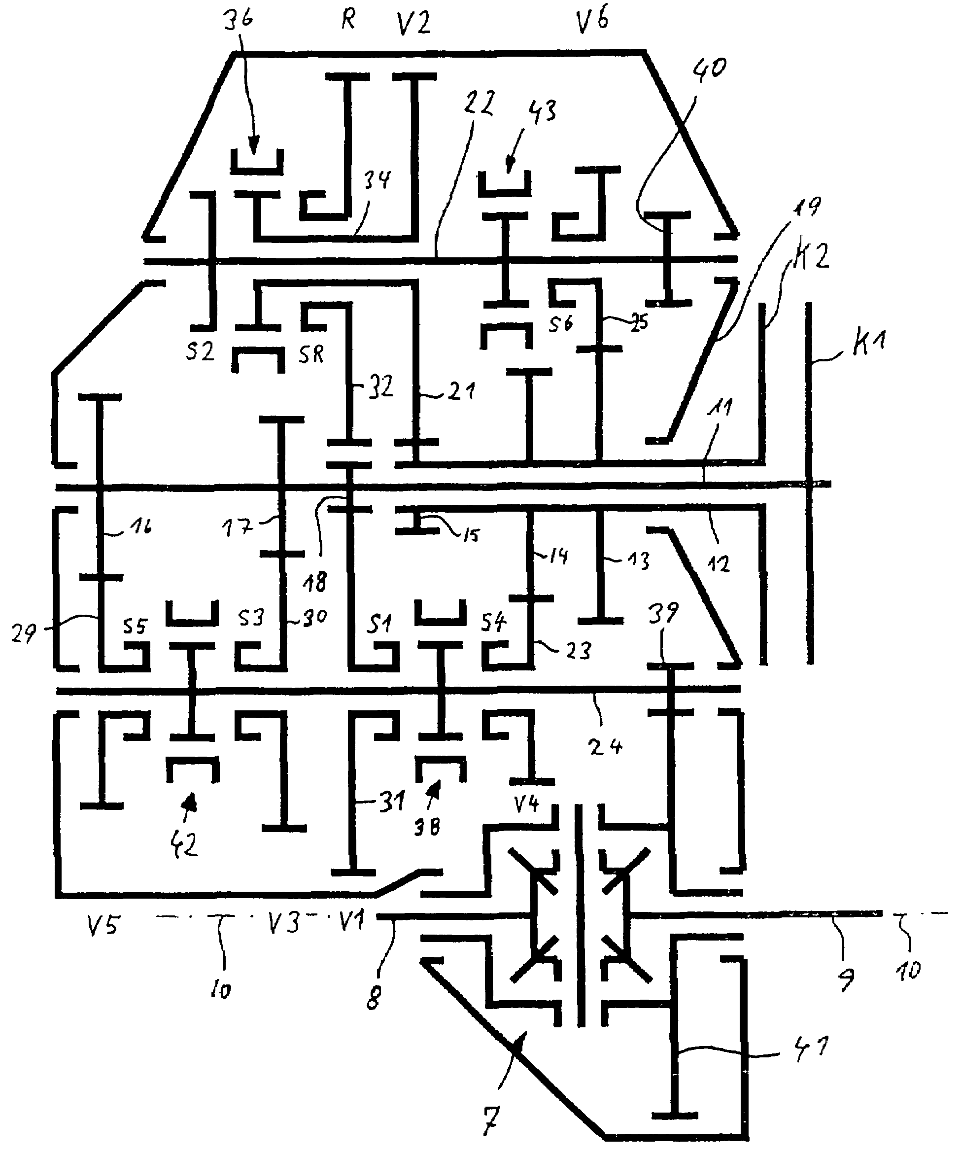
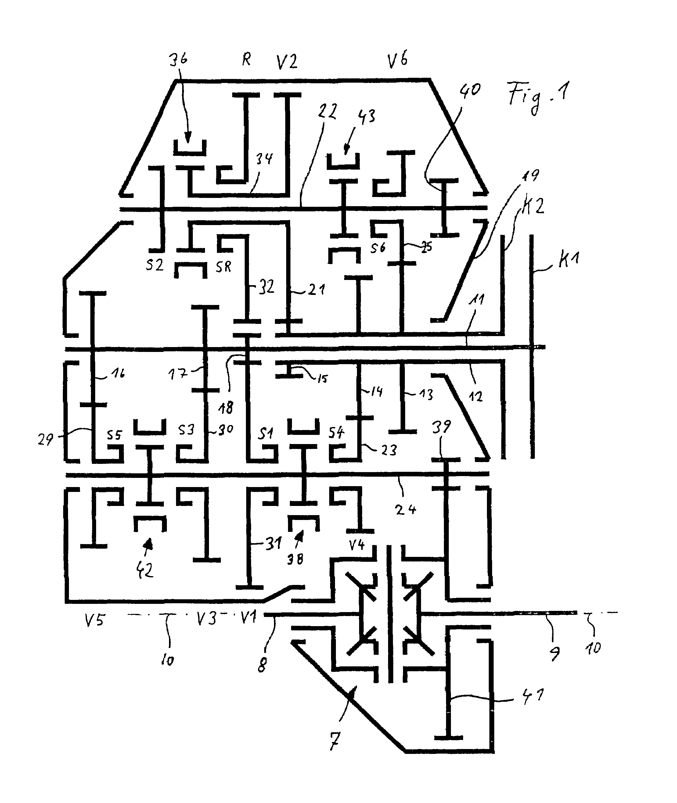
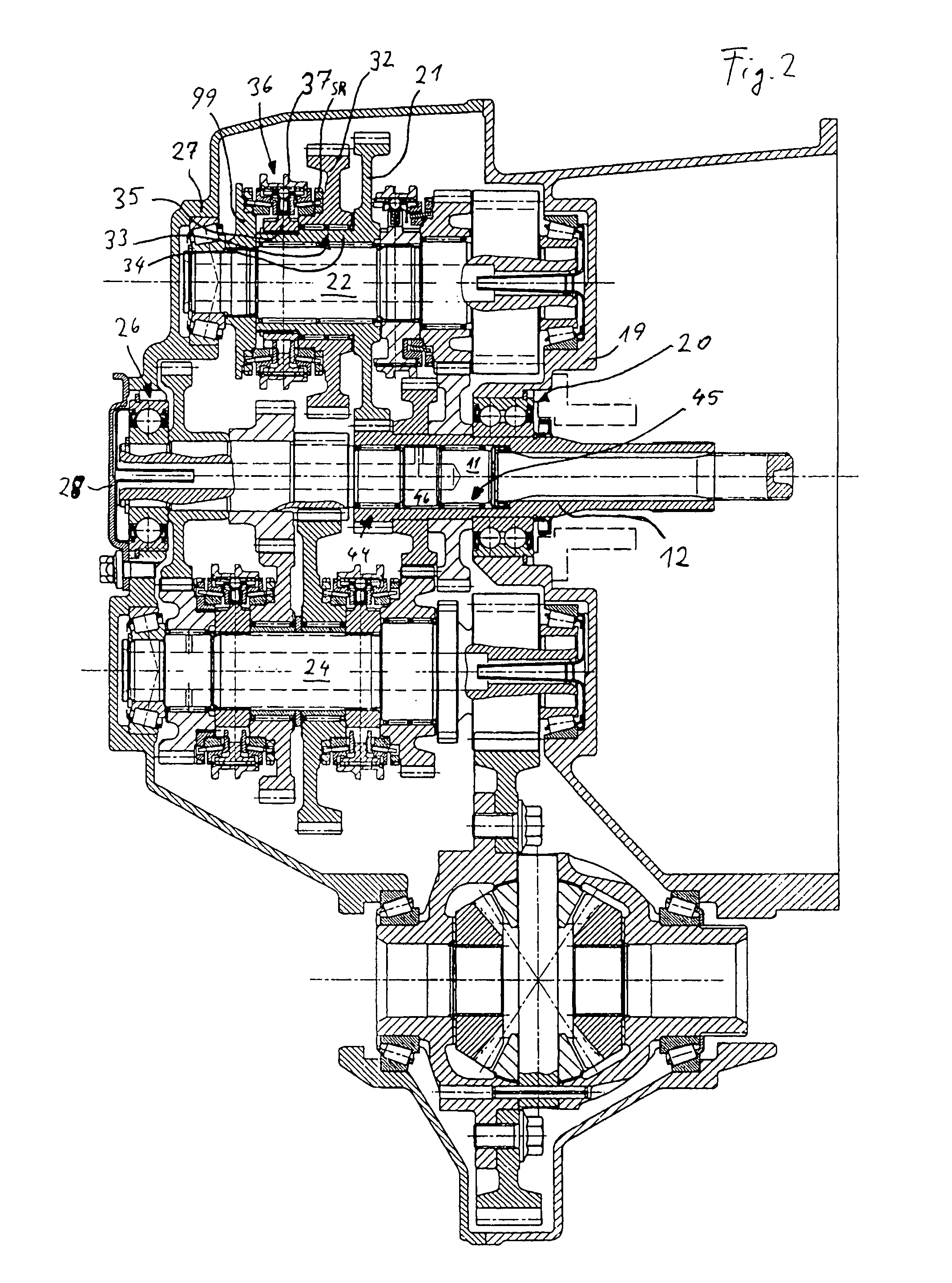
[0019]In the following description reference is made to FIG. 1 and FIG. 2 wherein design details however are sometimes shown only in FIG. 2, while FIG. 2 provides for a better overall view of the functional correlations of the various sets of gears. Shown is a double clutch transmission for transverse installation in the front of a motor vehicle. In the plane as shown in the Figs., an internal combustion engine is connected to the right end of the transmission. A differential drive 7 including the wheel drive shaft stubs 8, 9 for driving the front wheel drive axle 10 is shown in the Figs. at the bottom. The transmission shafts are shown for simplification in a single plane that is in the pane of the drawings. In reality, the four main shafts are displaced in parallel spatial relationship relative to one another.

[0020]The double clutch transmission includes two transmission input shafts 11, 12 of which one is a central input shaft 11 and the other is a hollow input shaft 12 through w...


PUM


Abstract

In a double clutch transmission, particularly for front wheel drive cars with transversely mounted engines, the power path for the reverse speed extends through the same path as that for the second forward speed, both using the same input clutch, while the power path for the first forward speed extends through the other input clutch of the double clutch so that shifting between the reverse and first speeds can be accomplished under engine power.

Description

BACKGROUND OF THE INVENTION[0001]The invention relates to a double clutch transmission particularly for front wheel drive cars including two spaced parallel secondary shafts wherein the direction of rotation of an output shaft can be changed by two selectively engageable friction clutches.[0002]Such a double clutch transmission is already known from DE 103 35 262.7.[0003]Furthermore, DE 196 24 857 discloses a three shaft transmission which is axially relatively short.[0004]It is the object of the present invention to provide a double-clutch transmission which is axially particularly short.SUMMARY OF THE INVENTION[0005]In a double clutch transmission particularly for front wheel drive cars with transversely mounted engines, the power path for the reverse speed extends through the same path as that for the second forward speed, both using the same input clutch while the power path for the first forward speed extends through the other input clutch of the double clutch so that shifting ...

Claims


Application Information

Patent Timeline
Patent Type & Authority Patents(United States)
IPC IPC(8): F16H3/08
CPCF16H3/006F16H3/093F16H2003/0931Y10T74/19228F16H2003/0807Y10T74/19233F16H2200/0052
Inventor RUEDLE, HARALD
Owner DAIMLER AG
Why Eureka
Try Eureka