Device for weighing substantially uniform weighing objects

a technology of substantially uniform weighing and weighing objects, which is applied in the direction of measuring devices, weighing apparatus, instruments, etc., can solve the problems of limiting the spatial dimensions of load carriers, and not being able to meet the requirements of complex conveyors, etc., to reduce the space requirement and optimize the heat distribution inside the housing

Active Publication Date: 2007-07-31
METTLER TOLEDO GMBH
View PDF10 Cites 19 Cited by
  • Summary
  • Abstract
  • Description
  • Claims
  • Application Information

AI Technical Summary

Benefits of technology

[0016]In another exemplary embodiment of the device for the weighing of substantially uniform weighing objects, a force-transmitting rod connected to a weighing module that is arranged on a lower plane is lengthened in comparison to a force-transmitting rod of a weighing module on a higher plane and may be provided with a sleeve to protect the force-transmitting rod. The difference in the preloads for different weighing modules which is due to the lengthening of the force-transmitting rod can be compensated. This compensation can be accomplished by means of a supplemental weight which is connected to the movable parallelogram leg of each weighing cell that belongs to a weighing module without a lengthened force-transmitting rod. This supplemental weight equals the weight that would, for example, be added by a lengthened force-transmitting rod. A supplemental weight is also provided for those weighing modules whose extension of the force-transmitting rod is not equal to the maximum length of a force-transmitting rod in the device. A supplemental weight which is interchangeable in a preferred embodiment of a weighing module can also serve the purpose of compensating for different sizes of weighing pans, or different sizes of the load carrier. The former as well as the latter can be interchangeable in order to provide flexibility in the use of the device for weighing substantially uniform weighing objects. However, for a given application of the device for weighing substantially uniform weighing objects or weighing objects of the same kind, the load carriers of the weighing modules used can all be of the same design.
[0021]The weighing modules in the device for the weighing of substantially uniform weighing objects are arranged in particular in such a way that they can be exchanged individually. If, for example, they are of uniform design. This enhances the service-friendliness of a device for the weighing of substantially uniform weighing objects as described herein. To allow individual weighing modules to be exchanged in a simple way, it may further be necessary to design the force-transmitting rod so that it can be separated from the weighing module.
[0023]Each weighing module of the device for the weighing of substantially uniform weighing objects is enclosed by a housing which has a shape that narrows down on the sides and / or from above towards the load receiver. This contributes to reducing the space requirement in a star-shaped arrangement. Also, the heat distribution inside the housing can be optimized in that the narrowing down of the housing from above keeps the heat away from the load receiver.

Problems solved by technology

The state-of-the-art microbalances as described in US 2003 / 0218467 have a disadvantage that, while being suitable for applications where masses in the microgram range need to be determined, they are not, for example, suited for the range of milligrams to grams.
In the case of weighing modules with large dimensions in comparison to the distances between the delivery elements of a conveyor device, even the star-like arrangement disclosed in the state of the art does not satisfy the requirements when a complex conveyor device is used, in particular of a type that is equipped with a two-dimensional arrangement of delivery elements.
Within the constraints of the given arrangement of the load carriers of the device for the weighing of like objects, a prerequisite in exemplary embodiments for the design of a load carrier is that it conforms to the given spatial or two-dimensional arrangement, meaning that the load carrier is limited in regard to its spatial dimensions.
In the case where the objects are delivered to the load carriers by a conveyor device, a malfunction of the latter can cause a randomly directed overload or transverse load to be applied to the load carrier and thus to the force-transmitting rod and the weighing cell of a weighing module.

Method used


Image

  • Device for weighing substantially uniform weighing objects
  • Device for weighing substantially uniform weighing objects
  • Device for weighing substantially uniform weighing objects

Examples


Embodiment Construction

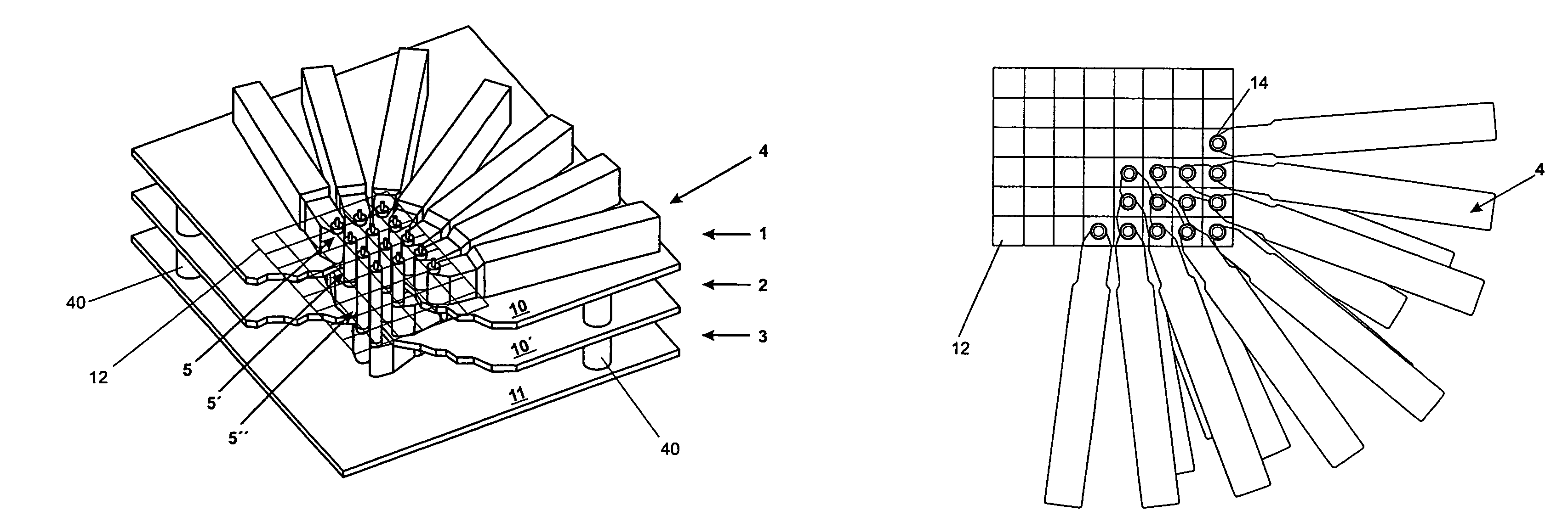
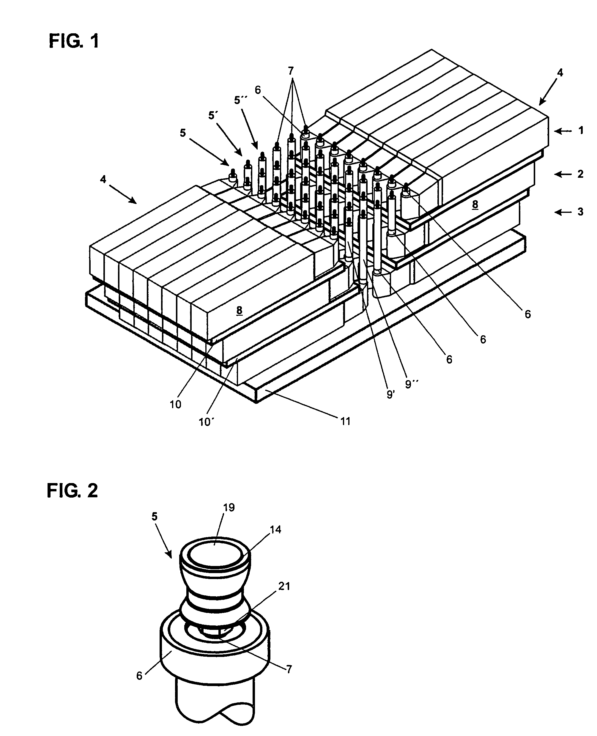
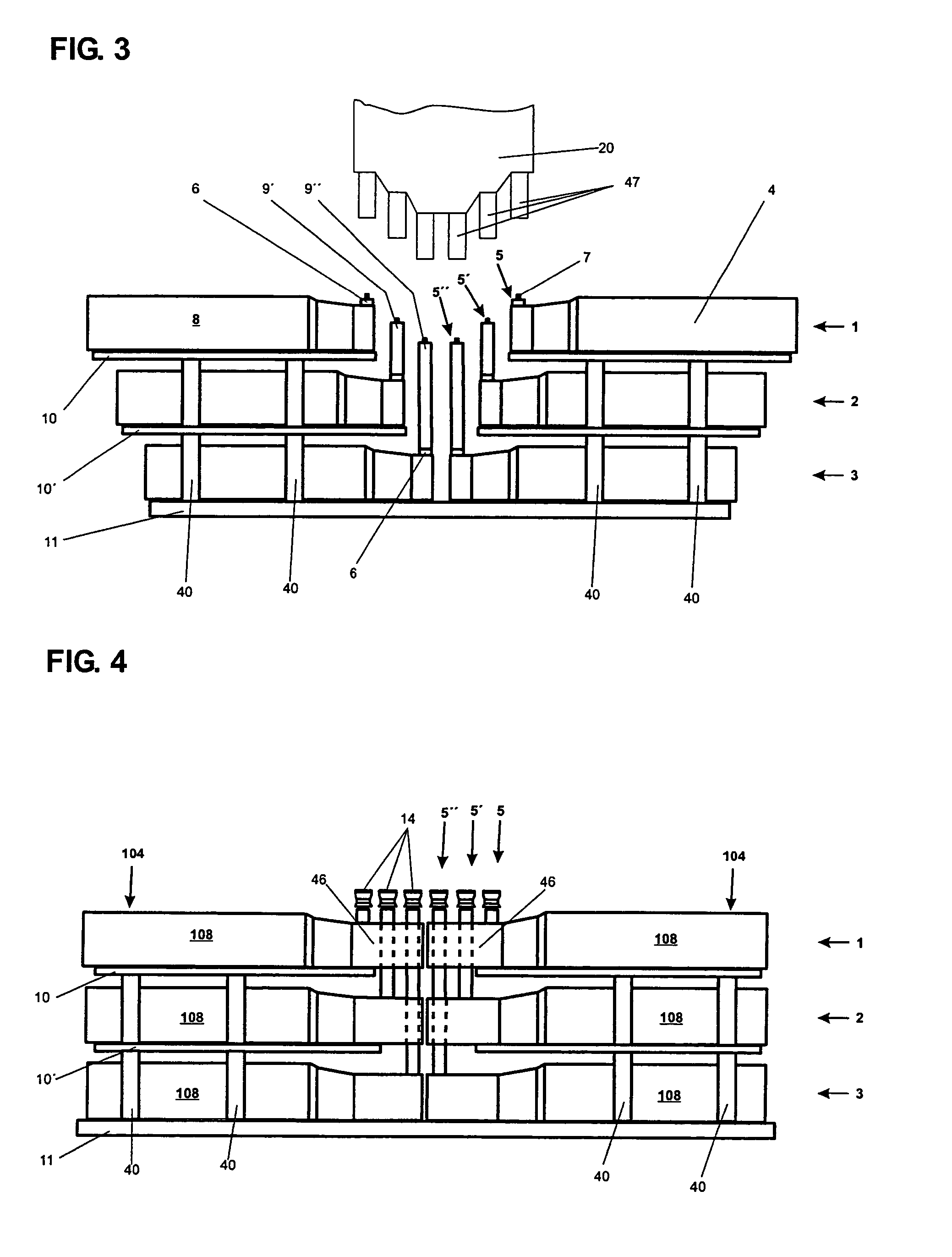
[0036]FIG. 1 shows in three-dimensional representation a device for the weighing of substantially uniform weighing objects that is built up from a total of forty-eight individual weighing modules 4. The weighing modules are arranged in three planes 1, 2, 3 on top of each other, forming in each of the planes 1, 2, 3 two rows of weighing modules 4 running parallel to each other, wherein the weighing modules 4 of the first plane 1 are arranged with a translatory offset in relation to the weighing modules of the second plane 2, in this case in the lengthwise direction of a weighing module 4. A weighing module 4 of the type illustrated here has a large lengthwise dimension in comparison to its width. The reason for this will be explained hereinafter in the context of FIG. 6.

[0037]Each of the weighing modules has a load receiver 5, 5′, 5″, with the load receivers 5, 5′, 5″ being arranged at regular intervals from each other. A load receiver 5, 5′, 5″ comprises at least a force-transmittin...


PUM


Abstract

A device to weigh substantially uniform weighing objects has a plurality of weighing modules and an equal number of load carriers that have central lengthwise axes extending in the direction of the load. Each of the load carriers is connected, respectively, to one of the weighing modules through a force-transmitting rod, and the load carriers are disposed in a given spatial or two-dimensional arrangement in which the distances between neighboring central lengthwise axes are smaller than the largest lengthwise extension of the respective weighing modules.

Description

RELATED APPLICATION[0001]This application claims priority to European Patent Application 05101587.3 filed in Europe on Mar. 2, 2005, the entire contents of which are hereby incorporated by reference.FIELD[0002]A device is disclosed which serves to weigh objects that are substantially uniform among each other, wherein the device has a plurality of weighing modules and an equal number of load carriers that have a central lengthwise axis extending in the direction of the load, wherein each of the load carriers is connected to one of the weighing modules, and wherein the load carriers are arranged in a given spatial or two-dimensional pattern in which the distances between neighboring central lengthwise axes are smaller than the largest lengthwise extension of a weighing module.BACKGROUND INFORMATION[0003]Exemplary devices in automated production- and testing systems include balances of a modular configuration—so-called weighing modules—particularly well suited to be integrally incorpor...

Claims


Application Information

Patent Timeline
Patent Type & Authority Patents(United States)
IPC IPC(8): G01G9/00G01G21/00
CPCG01G21/244
Inventor SCHILLING, PETERMEYERHANS, DOMINICMETZGER, ANDREASSCHUTZ, MARCELSCHEU, MATTHIASEMERY, JEAN-CHRISTOPHE
Owner METTLER TOLEDO GMBH
Why Eureka
Try Eureka