Battery with a Heat Conducting Plate

a technology of heat conducting plate and battery, which is applied in the field of batteries with heat conducting plates, can solve the problems of bursting of the cell housing of the respective single cells, high pressure build-up, and the effective heat conducting cross section of the heat conducting plate, and achieves the effects of increasing the stability of the entire battery housing, reducing the risk of bursting, and improving the tolerance of the battery housing

Inactive Publication Date: 2010-04-29
DAIMLER AG
View PDF4 Cites 30 Cited by
  • Summary
  • Abstract
  • Description
  • Claims
  • Application Information

AI Technical Summary

Benefits of technology

[0008]In a further arrangement of the invention, the spacer comprises a spacing collar extending radially from the pole and progressing at the edge of the insert piece in an uninterrupted continuous manner. With the spacing collar, a safe distance between the heat conducting plate and the cell cover is ensured, among other things, during mounting, even with higher tolerances and/or a careless assembly (for example, rotation of the insert piece).
[0009]In a further arrangement of the invention, the insert piece is made of a heat-conducting material, so that the pole can also be used for the heat management.
[0010]In a further arrangement of the invention, both poles of a single cell have a single (preferably one-piece) insert piece. This arrangement ensures a safe distance between the heat conducting plate and the cell cover, among other things during mounting, even with higher tolerances and/or a careless assembly, such as rotation of the insert piece.
[0011]In a further arrangement of the invention, the insert piece surrounds the outer surface of a pole especially completely, so that a safe conducting plate can be realized.
[0012]In a further...

Problems solved by technology

Especially with Li ion batteries, an overload and/or a high current withdrawal can lead to a high pressure build-up of the single cells, which can finally lead to bursting of the cell hou...

Method used


Image

  • Battery with a Heat Conducting Plate
  • Battery with a Heat Conducting Plate
  • Battery with a Heat Conducting Plate

Examples


Embodiment Construction

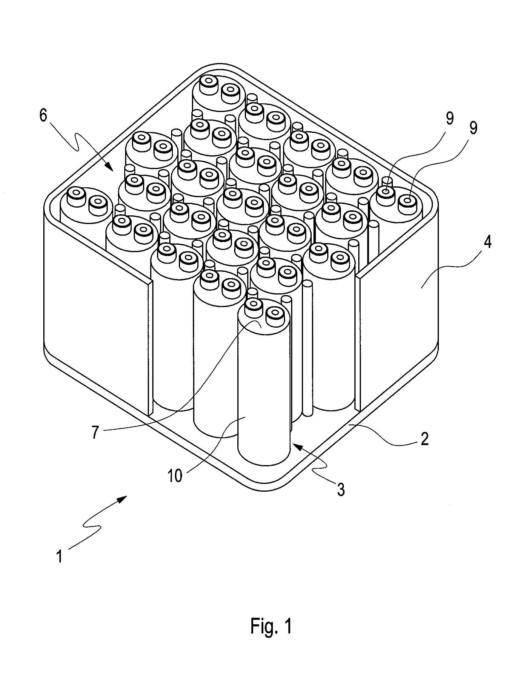
[0022]In FIG. 1 shows a known battery 1, which has a heat conducting plate 2 arranged at the bottom, and includes several single cells 3 connected electrically to one another. The single cells 3, which are preferably round in their cross section, are arranged preferably in a completely closed battery housing 4. Within the battery housing 4, the single cells 3 are placed on and thermally coupled to the heat conducting metal plate 2. Cooling channels 5 (FIG. 6) for conveying a heat conducting medium are arranged in the heat conducting plate 2. The single cells 3 are arranged on the heat conducting plate 2 with their longitudinal axes parallel to one another.

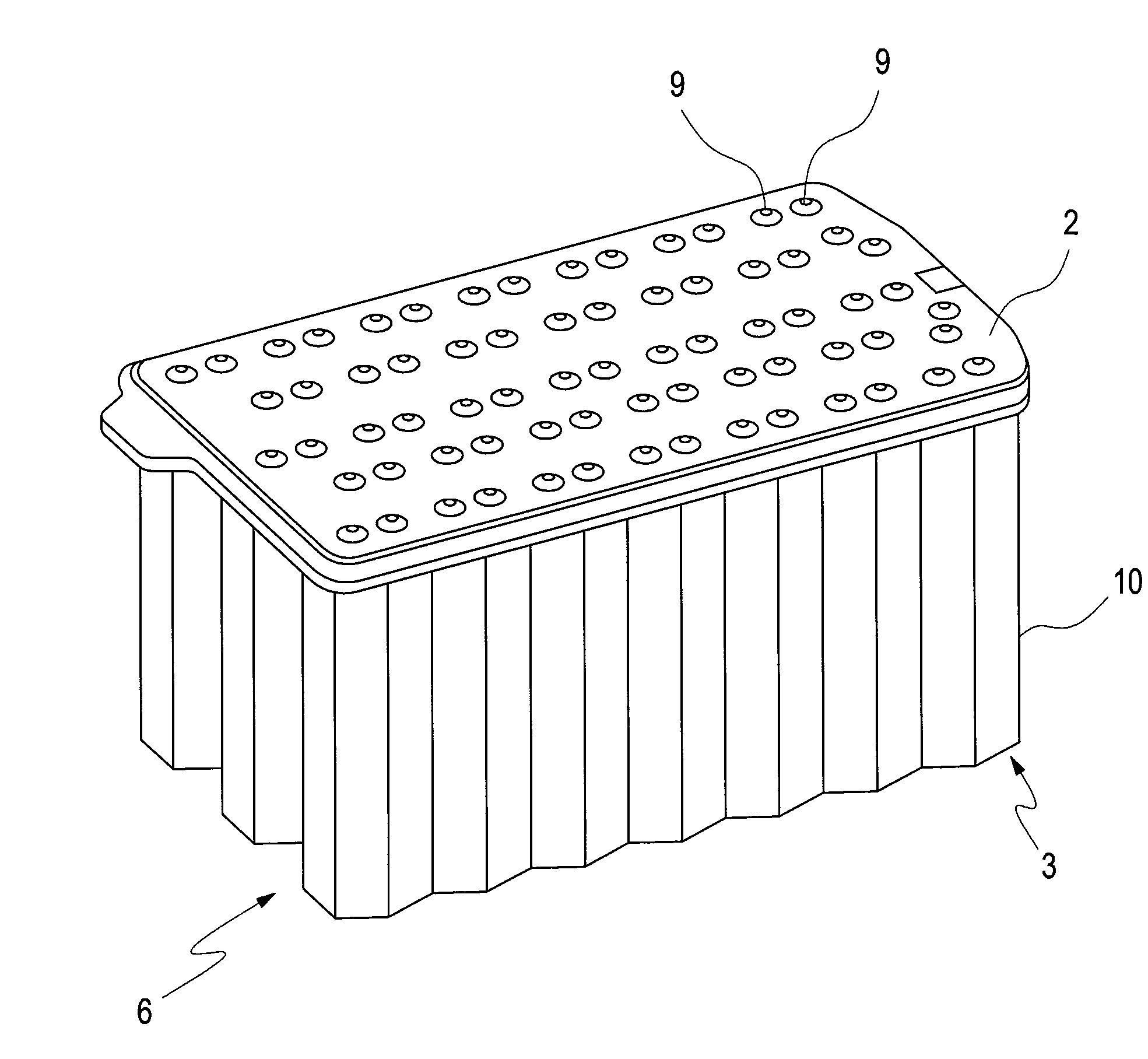
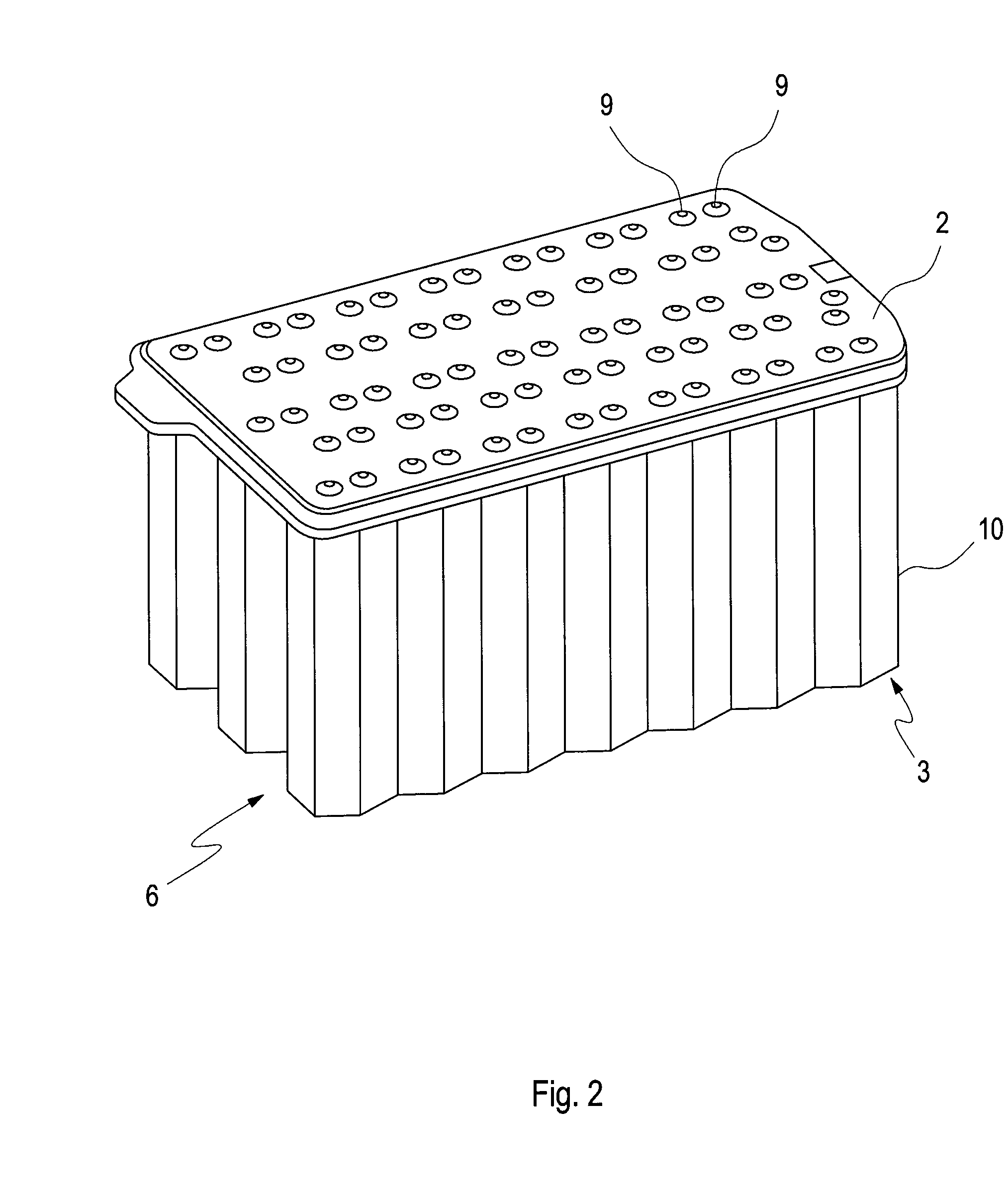
[0023]FIG. 2 is a perspective view of a cell stack 6 formed of several single cells 3 of a battery according to the invention, with a heat conducting plate 2 arranged at the top, so that the single cells 3 are thermally coupled. Especially due to the packing density of the single cells 3 of the present cell stack 6, the cross secti...


PUM


Abstract

A battery has a heat conducting plate for temperature control, and a plurality of parallel and/or serially connected single cells which are thermally coupled to the heat conducting plate. A channel structure is arranged in the heat conducting plate for guiding a flow of a heat conducting medium therein, and connection cross sections for the channel structure extend from the heat conducting plate. In the region of the poles of the single cells the heat conducting plate has bores through which the poles of the single cells extend. An insert piece which is made from an electrically insulating material and is arranged around the pole of a single cell, at least partially abuts the outer surface of the pole, and has at least one spacer extending radially from the pole. The spacer is arranged in the region of the pole between the cover of the single cell and the heat conducting plate.

Description

BACKGROUND AND SUMMARY OF THE INVENTION[0001]This application is a national stage of PCT International Application No. PCT / EP2008 / 001528, filed Feb. 27, 208, which claims priority under 35 U.S.C.§119 to German Patent Application No. 10 2007 010 745.7, filed Feb. 27, 2007, the entire disclosure of which is herein expressly incorporated by reference.[0002]The invention relates to a battery with a heat conducting plate for temperature control of the battery.[0003]Germany patent document DE 197 24 020 A1 discloses a battery that has several single cells connected in parallel and / or in series, which are placed on a heat conducting plate, and are in thermal contact therewith. An evaporator section of a heat pipe is arranged in the heat conducting plate. The heat pipe extends out of the heat conducting plate, and out of the battery housing, so that the condensation section of the heat pipe is outside the heat conducting plate. With this arrangement of the heat pipe, the heat conducting pla...

Claims


Application Information

Patent Timeline
IPC IPC(8): H01M10/50H01M50/179H01M50/213H01M50/502H01M50/55H01M50/559
CPCH01M2/06H01M2/08H01M2/1077H01M2/1094H01M2/206H01M10/5057H01M10/5004H01M10/5016H01M10/503H01M10/504H01M10/5053H01M2/305H01M10/625H01M10/653H01M10/6556H01M10/643H01M10/6554H01M10/613Y02E60/10H01M50/24H01M50/502H01M50/179H01M50/55H01M50/559H01M50/213
Inventor MEINTSCHEL, JENSSCHROETER, DIRKSCHULZ, PETRA
Owner DAIMLER AG
Why Eureka
Try Eureka