Linearisation of Scanned Data

a technology of scanned data and linearization, applied in the direction of program control, instruments, testing/monitoring control systems, etc., can solve the problems of criminals becoming more sophisticated, difficulty may be imposed, and complexity of technical knowledg

Inactive Publication Date: 2009-12-10
INGENIA HLDG LTD
View PDF65 Cites 26 Cited by
  • Summary
  • Abstract
  • Description
  • Claims
  • Application Information

AI Technical Summary

Benefits of technology

[0011]Further, both the instantaneous velocity and a velocity of the relative motion recorded during an earlier obtaining of a signature from an article may be used to linearise the positions of the groups of data points within the set of data points. This can compensate for any differences in the overall relative velocity compared to the velocity at which an earlier signature was obtained. The current signature is hence scaled to match the size of the earlier signature. Comparison of the signatures for authentication purposes is thereby facilitated.
[0013]The coherent radiation from the optical source and the illuminating radiation from the second optical source may have different wavelengths. This can help to differentiate between the two, so that the signature data and the images can be detected without contamination or interference by radiation used for the other.

Problems solved by technology

Many traditional authentication systems rely on a process which is difficult for anybody other than the manufacturer to perform, where the difficulty may be imposed by expense of capital equipment, complexity of technical know-how or preferably both.
Unfortunately, criminals are becoming more sophisticated and can reproduce virtually anything that original manufacturers can do.
Furthermore, such systems are typically too expensive and complicated for tasks such as product tracking for quality control and warranty purposes.
However, such systems are often still too expensive and / or complicated for tasks such as product tracking for quality control and warranty purposes.
Any variations in the scan rate for the subsequent scanning can produce a scan output which is distorted compared to the original scan, making matching of the scan output to the original scan data difficult.
This can result in the rejection of an authentic article.

Method used


Image

  • Linearisation of Scanned Data
  • Linearisation of Scanned Data
  • Linearisation of Scanned Data

Examples


Embodiment Construction

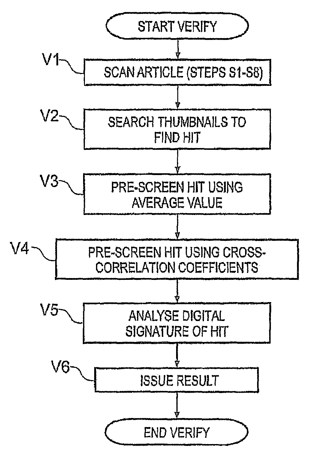
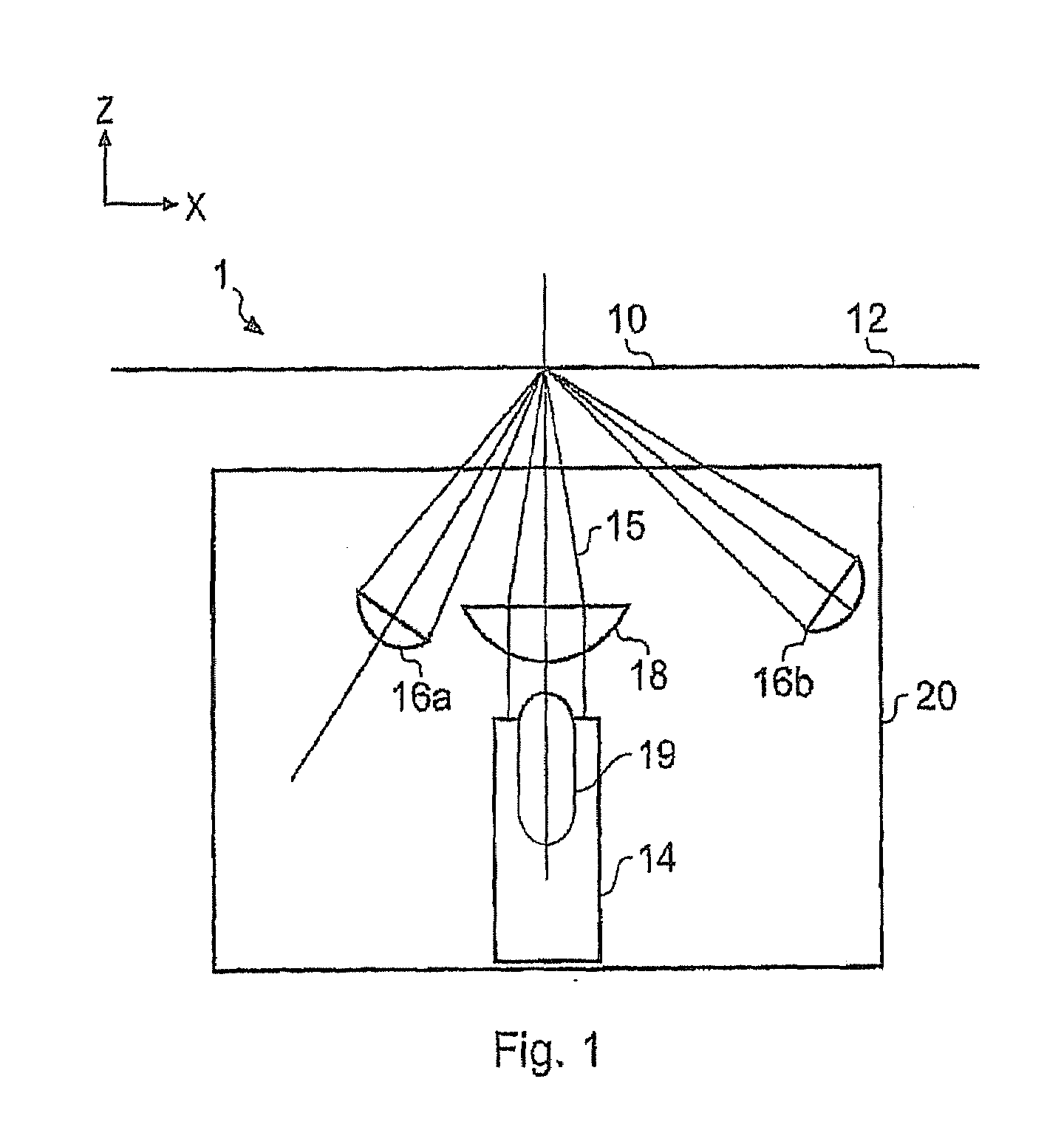
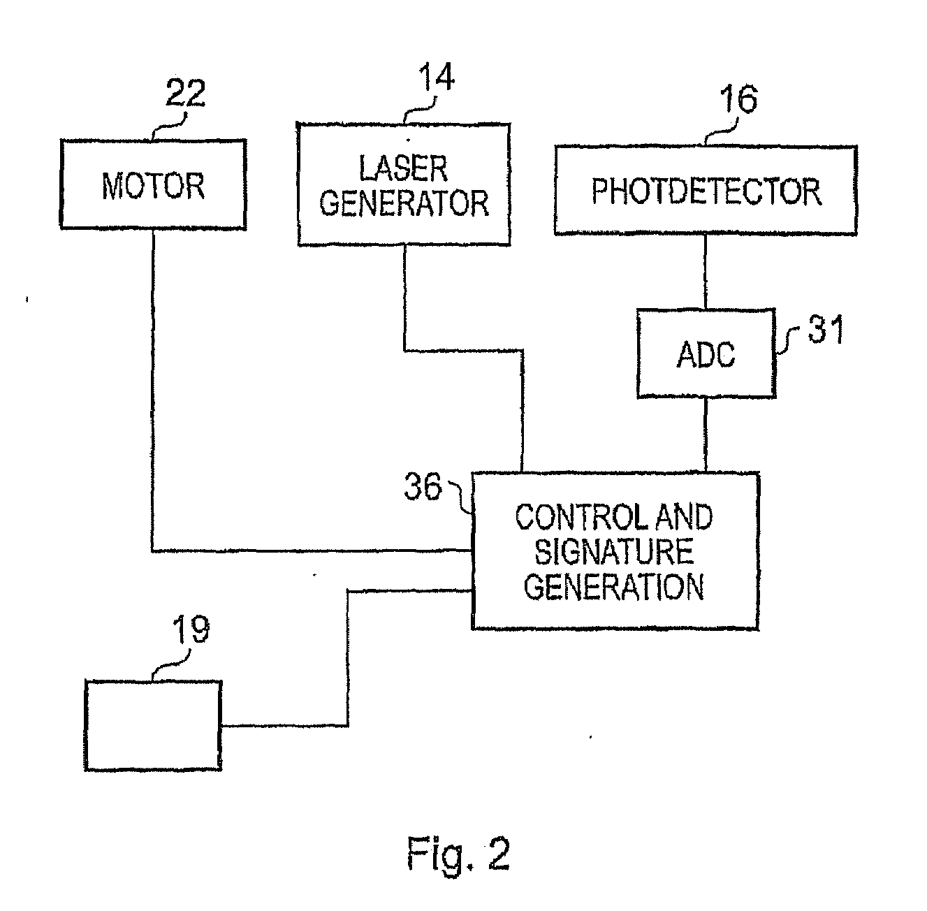
[0031]To provide an accurate method for uniquely identifying an article, it is possible to use a system which relies upon optical reflections from a surface of the article. An example of such a system will be described with reference to FIGS. 1 to 10.

[0032]The example system described herein is one developed and marketed by Ingenia Technologies Ltd. This system is operable to analyse the random surface patterning of a paper, cardboard, plastic or metal article, such as a sheet of paper, an identity card or passport, a security seal, a payment card etc to uniquely identify a given article. This system is described in detail in a number of published patent applications, including GB0405641.2 filed 12 Mar. 2004 (published as GB2411954 14 Sep. 2005), GB0418138.4 filed 13 Aug. 2004 (published as GB2417707 8 Mar. 2006), U.S. 60 / 601,464 filed 13 Aug. 2004, U.S. 60 / 601,463 filed 13 Aug. 2004, U.S. 60 / 610,075 filed 15 Sep. 2004, GB 0418178.0 filed 13 Aug. 2004 (published as GB2417074 15 Feb....


PUM


Abstract

A system for obtaining a signature a scan area on the surface of an article comprises: a signature generator that generates the signature from scattered coherent radiation detected from a plurality of regions on the surface by using relative motion between the article and a scan head comprising a coherent radiation source and photodetectors to obtain a set of data points comprising a group of data points from each region; an imaging detector that captures a sequence of images of the surface during the relative motion; and a processor that calculates the instantaneous velocity of the relative motion; whereby the signature generator uses the instantaneous velocity to linearise the groups of data point within the set of data points before generating the signature of the article from the set of data points.

Description

CROSS-REFERENCE TO RELATED APPLICATIONS[0001]This application is based upon and claims the benefit of priority from the prior U.S. Patent Application No. 61 / 055,766, filed May 23, 2008, and prior GB Patent Application No. 0809502.8, filed May 23, 2008 both of which are hereby incorporated herein by reference in their entirety.BACKGROUND OF THE INVENTION[0002]The present invention relates to a scanner for obtaining a signature from an article which can be used for authentication of the article, and a method for obtaining such a signature.[0003]Many traditional authentication systems rely on a process which is difficult for anybody other than the manufacturer to perform, where the difficulty may be imposed by expense of capital equipment, complexity of technical know-how or preferably both. Examples are the provision of a watermark in bank notes and a hologram on credit cards or passports. Unfortunately, criminals are becoming more sophisticated and can reproduce virtually anything th...

Claims


Application Information

Patent Timeline
Patent Type & Authority Applications(United States)
IPC IPC(8): G06F7/04H04N1/40
CPCG07D7/2033H04N2201/0081H04N2201/04731H04N2201/04787H04N2201/04791H04N2201/3236H04N2201/0471H04N2201/04734H04N2201/04737H04N2201/04768G06K7/10544G07D7/12G07D7/20G06V10/42
Inventor COWBURN, RUSSELL PAULBUCHANAN, JAMES DAVID RALPH
Owner INGENIA HLDG LTD
Why Eureka
Try Eureka