Power Supply System and Vehicle

a power supply system and power supply technology, applied in the field of power supply systems, can solve the problems of unwanted circulation current flowing between, voltage difference between voltage conversion units, and different response characteristics of voltage conversion units, so as to achieve the effect of avoiding damage to power storage units

Active Publication Date: 2009-11-05
DENSO CORP
View PDF3 Cites 29 Cited by
  • Summary
  • Abstract
  • Description
  • Claims
  • Application Information

AI Technical Summary

Benefits of technology

[0028]According to the present invention, a power supply system and a vehicle suppressing an unwanted circulation current caused between a plurality of voltage conversion units having voltage conversion capabilities different from each other, and avoiding damage to power storage units can be implemented.

Problems solved by technology

Such voltage conversion units having voltage conversion capabilities different from each other inevitably have different response characteristics, due to differences in inductance and the like.
Therefore, if the electric motor power management system disclosed in U.S. Pat. No. 6,608,396 is directly applied, a voltage difference may be caused between the voltage conversion units during transition such as immediately after system start-up, and an unwanted circulation current may flow between the power storage units through the voltage conversion units.
Such a circulation current may damage the power storage units.

Method used


Image

  • Power Supply System and Vehicle
  • Power Supply System and Vehicle
  • Power Supply System and Vehicle

Examples


first embodiment

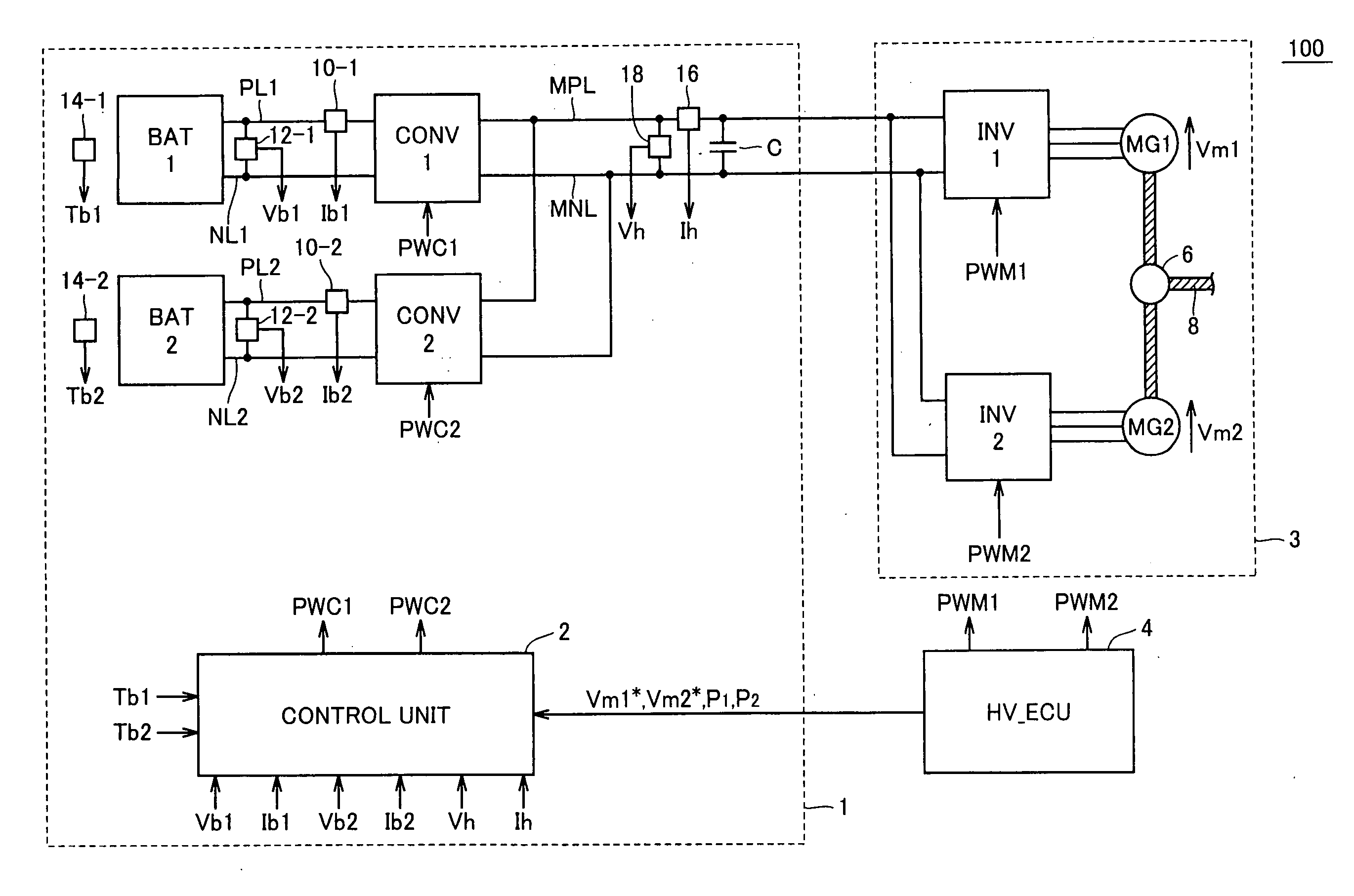
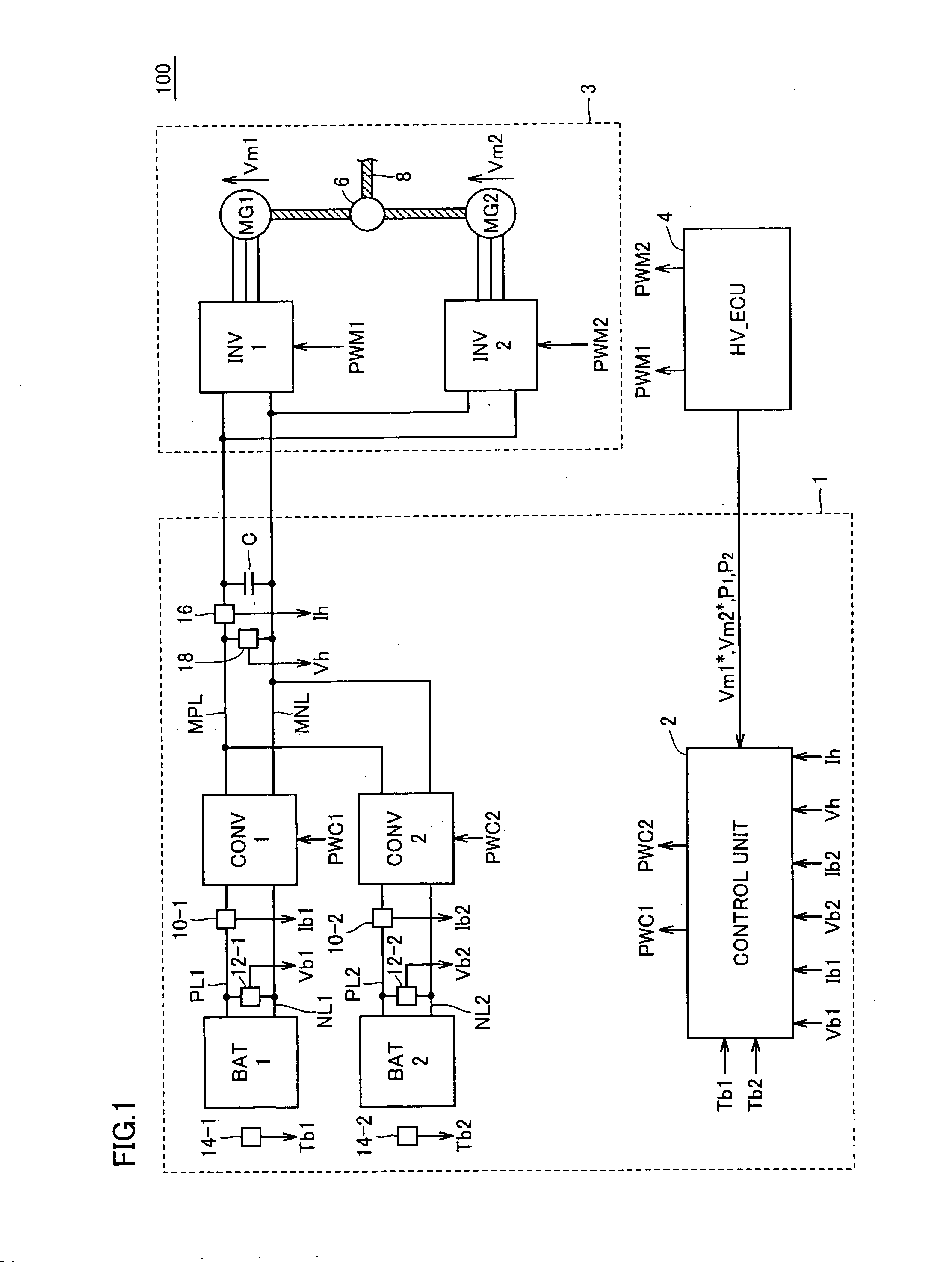
[0039]Referring to FIG. 1, a vehicle 100 including a power supply system 1 in accordance with a first embodiment of the present invention will be described. The first embodiment illustrates a case where a drive force generation unit 3 generating drive force for vehicle 100 is used as an example of a load device. Drive force generation unit 3 receives electric power from power supply system 1 to generate drive force, and supplies the drive force to wheels (not shown) of vehicle 100, causing vehicle 100 to run.

[0040]In the first embodiment, power supply system 1 having two power storage units as an example of a plurality of power storage units will be described. Power supply system 1 supplies and receives DC power to and from drive force generation unit 3 through a main positive bus line MPL and a main negative bus line MNL.

[0041]Drive force generation unit 3 includes a first inverter INV1, a second inverter INV2, a first motor-generator MG1, and a second motor-generator MG2, and gene...

second embodiment

[0115]The present invention is applicable to a power supply system having three or more power storage units, in addition to the power supply system having two power storage units described above.

[0116]Referring to FIG. 7, a vehicle 100# including a power supply system 1# in accordance with a second embodiment of the present invention will be described. Since vehicle 100# includes power supply system 1# arranged instead of power supply system 1 in vehicle 100 shown in FIG. 1, the detailed description of drive force generation unit 3 will not be repeated. In the second embodiment of the present invention, power supply system 1# including N power storage units will be described.

[0117]Power supply system 1# includes converters CONV1, CONV2, . . . , CONVN, power storage units BAT1, BAT2, . . . , BATN, battery current value detection units 10-1, 10-2, . . . , 10-N, battery voltage value detection units 12-1, 12-2, . . . , 12-N, and battery temperature detection units 14-1, 14-2, . . . , 1...


PUM


Abstract

Transfer functions of control have duty commands as inputs and battery current values as outputs, provided corresponding to respected converters. Control gains are determined such that certain transfer functions substantially match with each other, with respect to delay elements.

Description

TECHNICAL FIELD[0001]The present invention relates to a power supply system including a plurality of power storage units and a vehicle equipped with the vehicle system. In particular, the present invention relates to a technique suppressing a circulation current caused between power storage units.BACKGROUND ART[0002]In recent years, considering environmental issues, attention has been paid to a vehicle employing an electric motor as a source of drive force, such as an electric vehicle, a hybrid vehicle, and a fuel cell vehicle. Such a vehicle is equipped with a power storage unit implemented for example by a rechargeable battery for supplying electric power to the electric motor and converting kinetic energy to electric energy during regenerative braking.[0003]In such a vehicle employing an electric motor as a source of drive force, it is desirable to further increase a battery capacity of a power storage unit to improve acceleration performance and running performance such as a max...

Claims


Application Information

Patent Timeline
Patent Type & Authority Applications(United States)
IPC IPC(8): B60L1/00
CPCB60L11/1851Y02T10/7275H02M2001/0025Y02T10/7005B60L2210/10Y02T10/7077Y02T10/7241Y02T10/7061Y02T10/7216Y02T10/6217Y02T10/642B60L7/14B60L11/123B60L11/14B60L11/1864B60L15/2009B60L2210/40B60L2240/421B60L2240/423B60L2240/545B60L2240/547B60L2240/549B60L2200/26H02J1/102B60L50/61B60L50/16B60L58/10B60L58/21Y02T10/62Y02T10/64Y02T10/70Y02T10/72Y02T10/7072H02M1/0025
Inventor ICHIKAWA, SHINJI
Owner DENSO CORP
Why Eureka
Try Eureka