
Voltage control system

a voltage control and load technology, applied in the direction of process and machine control, instruments, light sources, etc., can solve the problems of large energy cost, large cost, and more complex timing sequence, etc., to facilitate voltage transition, reduce cost, and reduce the effect of circuit siz

Inactive Publication Date: 2007-07-31
748038 ONTARIO INC
View PDF18 Cites 4 Cited by
  • Summary
  • Abstract
  • Description
  • Claims
  • Application Information

AI Technical Summary

Benefits of technology

"The present invention provides a circuit for controlling the voltage applied to an output voltage terminal from a first voltage level supplied by an input voltage terminal. The circuit includes a transformer and two switches connected in series between the input voltage terminal and the output voltage terminal. The switches are connected in parallel with an output transformer. The circuit allows for a smooth transition of voltages without causing significant current interruption that would extinguish the arc in the load and require it to be restarted at full voltage. The circuit also provides a simple and reliable means of reducing energy usage and promoting energy savings. The invention also provides a method to efficiently achieve a voltage reduction to un-interruptible loads."

Problems solved by technology

Lighting, and more specifically high intensity discharge (HID) lighting, makes up a large portion of the energy costs at many industrial, commercial, and public facilities.
These methods usually have the drawback of being too costly and / or too complex.
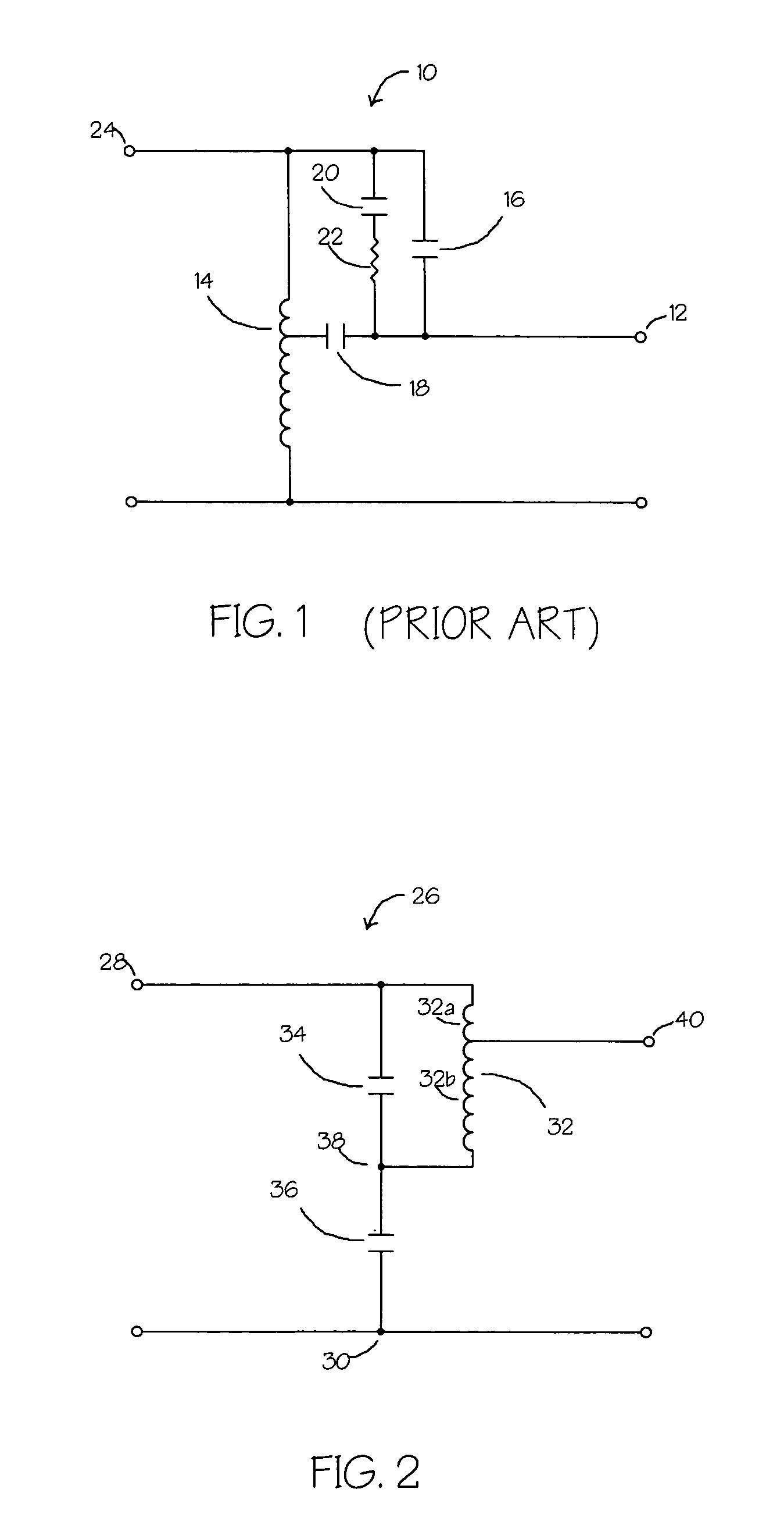
This prior apparatus has several drawbacks such as the fact that the third switch 20 is required to facilitate the transition between the first and second voltages.
Moreover, this method requires four switching operations (and therefore a more complex timing sequence) to transition from the first voltage level to the second voltage level.

Method used


Image

  • Voltage control system
  • Voltage control system
  • Voltage control system

Examples


Embodiment Construction

[0034]Generally, the present invention provides a method and system for controlling voltage to a load, such as in a lighting system.

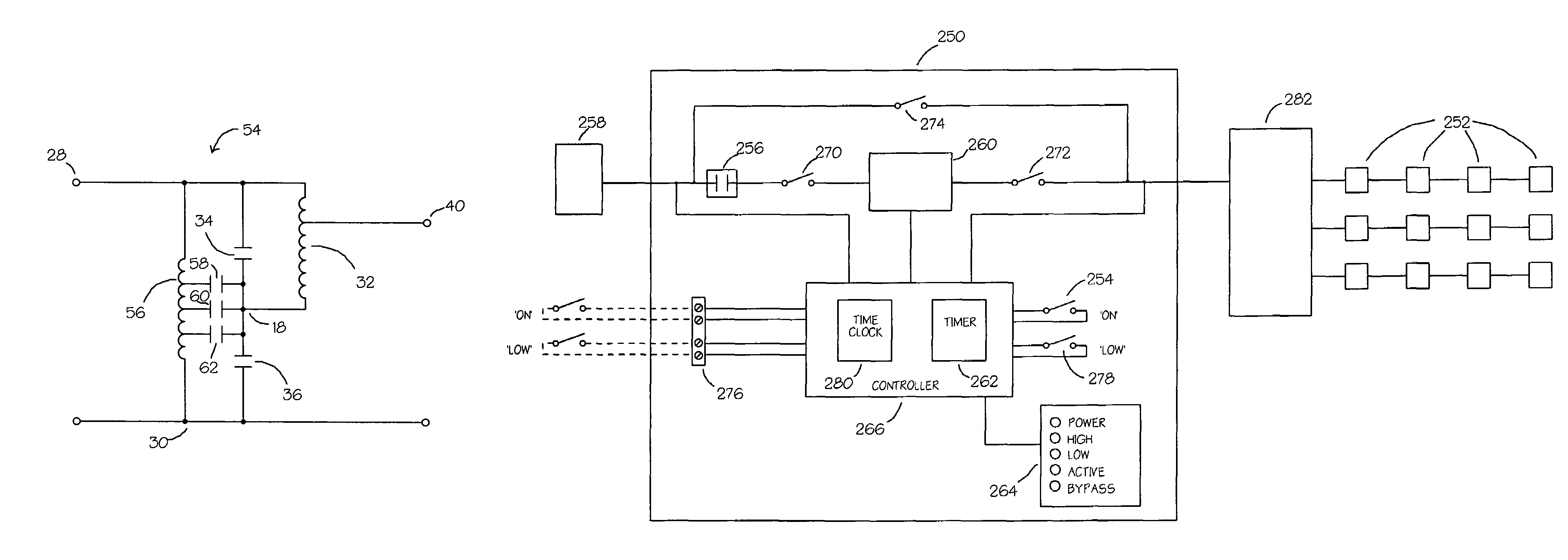
[0035]Turning to FIG. 16, a schematic diagram of apparatus for controlling the voltage supplied to a lighting load is shown. Although, the invention is preferably directed at providing a circuit for controlling a lighting load, it will be understood that this voltage control circuitry may also be implemented in motors.

[0036]The apparatus 250 is connected to at least one lighting load 252. Generally, the apparatus 250 is located in front of an individual lighting circuit or in front of a common connection point of a multitude of lighting circuits, i.e. a lighting panel 282.

[0037]When a user activates the lighting load, by turning on a lighting switch 254, a main contactor 256 is closed in order to apply a voltage 258 to a circuit 260 for controlling the voltage (which will be described in more detail below). It will be understood that the lighting switch...


PUM


Abstract

The present invention is directed at circuit for controlling a voltage applied to an output voltage terminal from a first voltage level supplied by an input voltage terminal comprising a first switch and a second switch connected in series between said input voltage terminal and a common terminal; a transformer, having a primary side and a second side, connected with said first switch on the primary side and to said output terminal on the secondary side; wherein when said first switch is closed and said second switch open, said first voltage level is supplied to said output voltage terminal; and wherein when said first switch is open and said second switch is closed, a second voltage level is supplied to said output voltage terminal.

Description

CROSS REFERENCE TO RELATED APPLICATIONS[0001]This application claims the benefit of U.S. Provisional Application No. 60 / 479,843, filed Jun. 20, 2003, which is incorporated herein by reference.FIELD OF THE INVENTION[0002]The present invention relates generally to supplying voltage to loads and more particularly, the present invention relates to apparatus for reducing the voltage supplied to loads.BACKGROUND OF THE INVENTION[0003]Lighting, and more specifically high intensity discharge (HID) lighting, makes up a large portion of the energy costs at many industrial, commercial, and public facilities. In many cases, full light output is not required during certain hours of the day or under specific operating conditions. Therefore, in order to achieve costs savings, it would be beneficial to control this lighting source in order to provide substantial energy cost reductions.[0004]Currently, methods and apparatus exist to reduce the applied voltage to an HID load in a stepwise manner usin...

Claims


Application Information

Patent Timeline
Patent Type & Authority Patents(United States)
IPC IPC(8): G05F1/14G05F5/00H05B41/16H05B41/40H05B41/42
CPCH05B41/40H05B41/42
Inventor MCVICAR, RANDY
Owner 748038 ONTARIO INC
Learn More