Current mode switching regulator with predetermined on time

a current mode switching and predetermined technology, applied in the field of switching regulators, can solve the problems of insufficient use in many applications, insufficient i>a/i>) and prior art techniques, and achieve the effects of improving the regulation accuracy of output voltage, reducing ripple current value, and superior light load efficiency

Inactive Publication Date: 2007-07-31
COLLABO INNOVATIONS INC
View PDF37 Cites 105 Cited by
  • Summary
  • Abstract
  • Description
  • Claims
  • Application Information

AI Technical Summary

Benefits of technology

[0020]One advantage of the present invention is that it provides a current mode switching regulator with the capability of operating at switch ON duty cycles of up to 100% that can be implemented without the use of slope compensation by utilizing a predetermined value of switch ON time TON.
[0021]Another advantage of the present invention is to provide a controller which employs an integration of error between the desired and actual values of output voltage in order to improve the regulation accuracy of the output voltage beyond that provided by controllers having only proportional error control.
[0022]Another advantage is that the controller of the present invention operates in both the discontinuous inductor current mode “DCM” at small values of load current to thereby provide superior light load efficiency, and the continuous inductor current mode “CCM” at large values of load current for the purpose of reducing the value of ripple current in the inductor and output capacitor (and therefore the ripple voltage at voltage output) as well as providing superior efficiency at heavy loads.
[0023]Yet another advantage is the automatic transition realized between DCM and CCM and the use of current mode control provides rejection of both load current and input voltage changes in the output voltage as well as minimizes changes in transient response time as a function of load current operating point.
[0024]Another advantage is that the circuit of the present invention employs continuous time direct monitoring without a sampling clock of the error signal before the loop filter, which eliminates the delays due to filter slew rate and clock period.

Problems solved by technology

While the foregoing circuitry is operable as a switching regulator, it is inadequate for use in many applications including, for example, portable battery powered devices (e.g., cell phones).
The prior art technique described above and illustrated in FIG. 1(a) is inadequate because it suffers from significant losses due to a forward voltage drop in the diode 137.
Nonetheless, this approach requires significant changes to the controller in order to generate the proper gate drive signal for the MOS transistor switch.
If both switches are ON at the same moment for even a short period of time, a large shoot-through current flows from the input voltage VIN to ground GND, which can dramatically impair the efficiency of the circuit and even possibly damage the switches due to overheating.
Conversely, if both switches are turned OFF simultaneously, “dead time” or a non-conducting period is generated, causing the inductor current to flow through the body diodes of the switches and resulting in power losses due to the large forward voltage drop of the diodes.
However, this prior art is defective in that the additional components associated with this learning circuit increase cost and design complexity to the point where the design is no longer a practical solution for many applications.
Another disadvantage of the conventional method, as illustrated in the regulator of FIG. 1(a), results from the additional reduction in efficiency caused by switching losses in the gate drives for the MOS switches.
Such switching regulators are also not maximally effective from an efficiency viewpoint since it still allows multiple switching cycles during the burst.
Another shortcoming of the fixed frequency current mode switching regulator shown in FIG. 1(a) results from an inherent stability problem when the duty cycle for switching TON to TCLOCK exceeds 50% (i.e. when the switch is ON for more than 50% of any given switching cycle).
The drawback of this method is that the implementation of such a control circuit adds a significant amount of electrical components to the switching regulator, resulting in increased size, cost and design complexity to the controller.

Method used


Image

  • Current mode switching regulator with predetermined on time
  • Current mode switching regulator with predetermined on time
  • Current mode switching regulator with predetermined on time

Examples


Embodiment Construction

[0035]The present invention now will be described more fully hereinafter with reference to the accompanying drawings, in which preferred embodiments of the invention are shown. This invention may, however, be embodied in many different forms and should not be construed as limited to the embodiments set forth herein: rather, these embodiments are provided so that this disclosure will be thorough and complete, and will fully convey the scope of the invention to those skilled in the art, like numbers refer to like elements throughout.

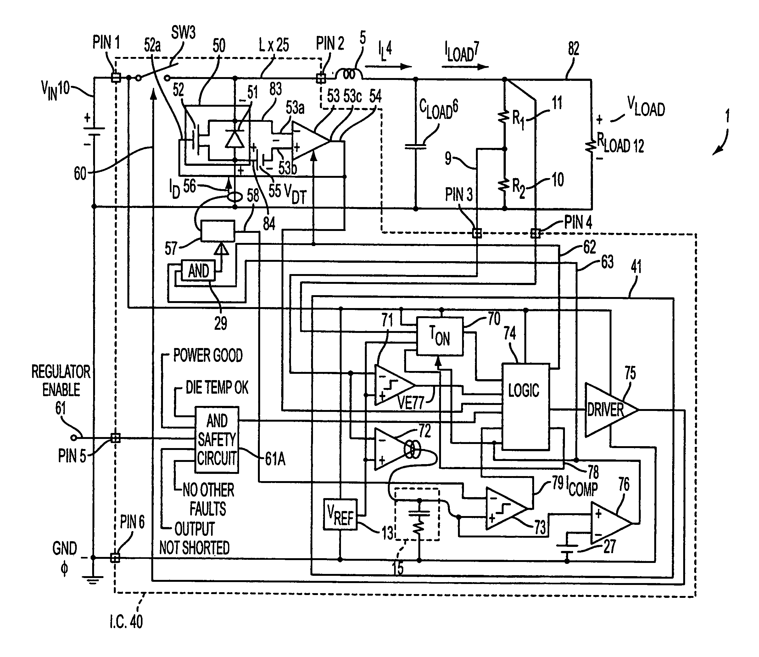
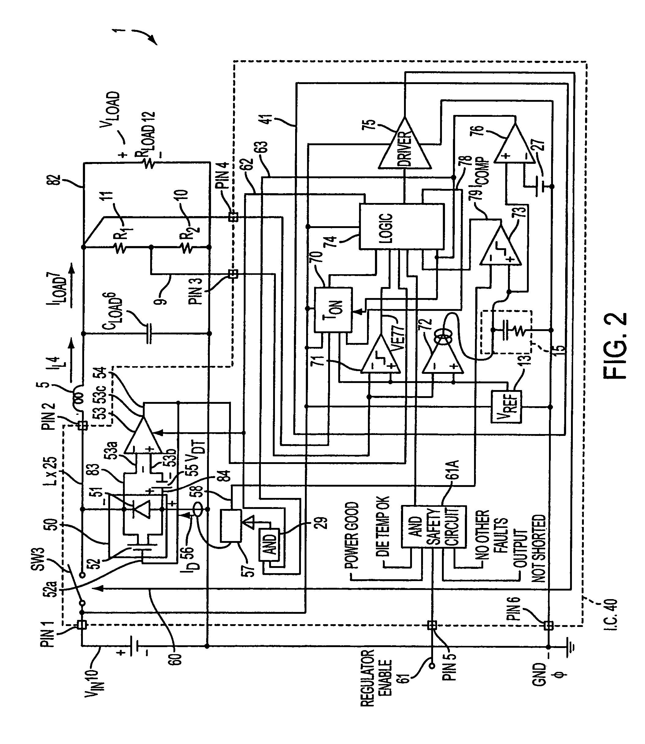
[0036]FIG. 2 illustrates an exemplary current mode switching regulator in accordance with the present invention. Referring to FIG. 2, in the given embodiment, the switching regulator 1 includes a voltage source VIN 10 having a first lead coupled to a first lead of a switch, SW3. VIN is preferably supplied by conventional sources such as batteries or other power sources, and the switch SW 3 is preferably a type of positive-channel metal-oxide semiconductor ...


PUM


Abstract

A power supply switching regulator including a common terminal; an input terminal for supplying a direct current input; an output terminal; a recirculating diode having a first terminal connected to the common terminal; an inductor having a first terminal connected to a second terminal of the recirculation diode and a second terminal connected to the output terminal; a capacitor having a first terminal connected to the output terminal and a second terminal connected to the common terminal; a switch connected between the input terminal and the first terminal of the inductor, the switch operable for switching between an ON state in which the direct current input is coupled to the inductor, and an OFF state in which the direct current input is isolated from the inductor; and a controller coupled to the switch and operable for controlling the amount of time the switch is in the ON state and the OFF state such that the duration of time the switch is in the ON state is inversely proportional to the difference between the voltage at the input terminal and the voltage at the output terminal.

Description

CLAIM OF PRIORITY[0001]This patent application, and any patent(s) issuing therefrom, claim priority to U.S. provisional patent application No. 60 / 557,695, filed on Mar. 31, 2004, which is incorporated herein by reference in its entirety.FIELD OF THE INVENTION[0002]The present invention relates to switching regulators, and more particularly, to switching regulators capable of high efficiency operation over a wide range of supply voltage and load current by utilizing a simplified dual mode controller that provides both good transient response and high steady state accuracy.BACKGROUND OF THE INVENTION[0003]As is known in the prior art, in order to provide a fast response to large changes in load current and input supply voltage, the most frequently used form of step down or buck switching regulator employs constant frequency peak current control. An example of such a prior art switching regulator is illustrated in FIG. 1(a). FIG. 1(b) contains timing diagrams illustrating discontinuous...

Claims


Application Information

Patent Timeline
Patent Type & Authority Patents(United States)
IPC IPC(8): G05F1/618G05F1/575G05F1/40H02M3/155H02M3/156
CPCH02M3/156
Inventor OSWALD, RICHARD K.YAMAMOTO, TAMOTSUSAITO, HIROSHIISHII, TAKUYARYU, TAKASHIAKASHI, HIROKITANAKA, TAKESHI
Owner COLLABO INNOVATIONS INC
Why Eureka
Try Eureka