Direct digital synthesis (DDS) phase locked loop (PLL) frequency synthesizer and associated methods

a frequency synthesizer and digital synthesis technology, applied in the field of direct digital synthesis (dds) phase locked loop frequency synthesizer and associated methods, can solve the problems of affecting the spectral purity of the vco, affecting the quality of the dds, so as to reduce the output spurs, reduce phase noise, and reduce the effect of phase nois

Inactive Publication Date: 2007-07-31
HARRIS CORP
View PDF6 Cites 25 Cited by
  • Summary
  • Abstract
  • Description
  • Claims
  • Application Information

AI Technical Summary

Benefits of technology

[0024]The frequency synthesizer and method have narrow frequency steps (e.g. as low as fractions of a Hertz) while using a relatively high reference frequency to maintain low phase noise. Furthermore, the fine frequency tuning resolution is achieved while also reducing output spurs and using a relatively simple topology.

Problems solved by technology

However, while it is possible to increase the reference frequency to reduce N, there are limitations to this approach.
While fractional-N dividers can be used to lessen the step size limitations of using higher reference frequencies, there are additional problems with using fractional-N dividers, specifically the generation of fractional spurs which corrupt the spectral purity of the VCO.
In sampler based synthesizers so-called crossing spurs may be a problem.
These mixing products are generally unwanted and therefore spurious signals.
Unfortunately, since these nth order mixing products share the frequency range with that of the sampler IF signal, they cannot be filtered out using a filter.
Unfortunately, reducing the frequency range of the sampler IF signal for a given synthesizer design requires a larger selection of sample frequencies fs to minimize the sample frequency fs gaps.
So there may be severe practical limitations on how narrow the sampler IF can be made in a given design.
Consequently, there are a number of conflicting requirements for the sampler-based PLL synthesizer.
The sampling signal should have a high frequency sampling signal frequency fs to minimize the harmonic number H. However, a small H requires the sample frequency fs to have a wider frequency range, making low phase noise more difficult to achieve.

Method used


Image

  • Direct digital synthesis (DDS) phase locked loop (PLL) frequency synthesizer and associated methods
  • Direct digital synthesis (DDS) phase locked loop (PLL) frequency synthesizer and associated methods
  • Direct digital synthesis (DDS) phase locked loop (PLL) frequency synthesizer and associated methods

Examples


Embodiment Construction

[0028]The present invention will now be described more fully hereinafter with reference to the accompanying drawings, in which preferred embodiments of the invention are shown. This invention may, however, be embodied in many different forms and should not be construed as limited to the embodiments set forth herein. Rather, these embodiments are provided so that this disclosure will be thorough and complete, and will fully convey the scope of the invention to those skilled in the art. Like numbers refer to like elements throughout.

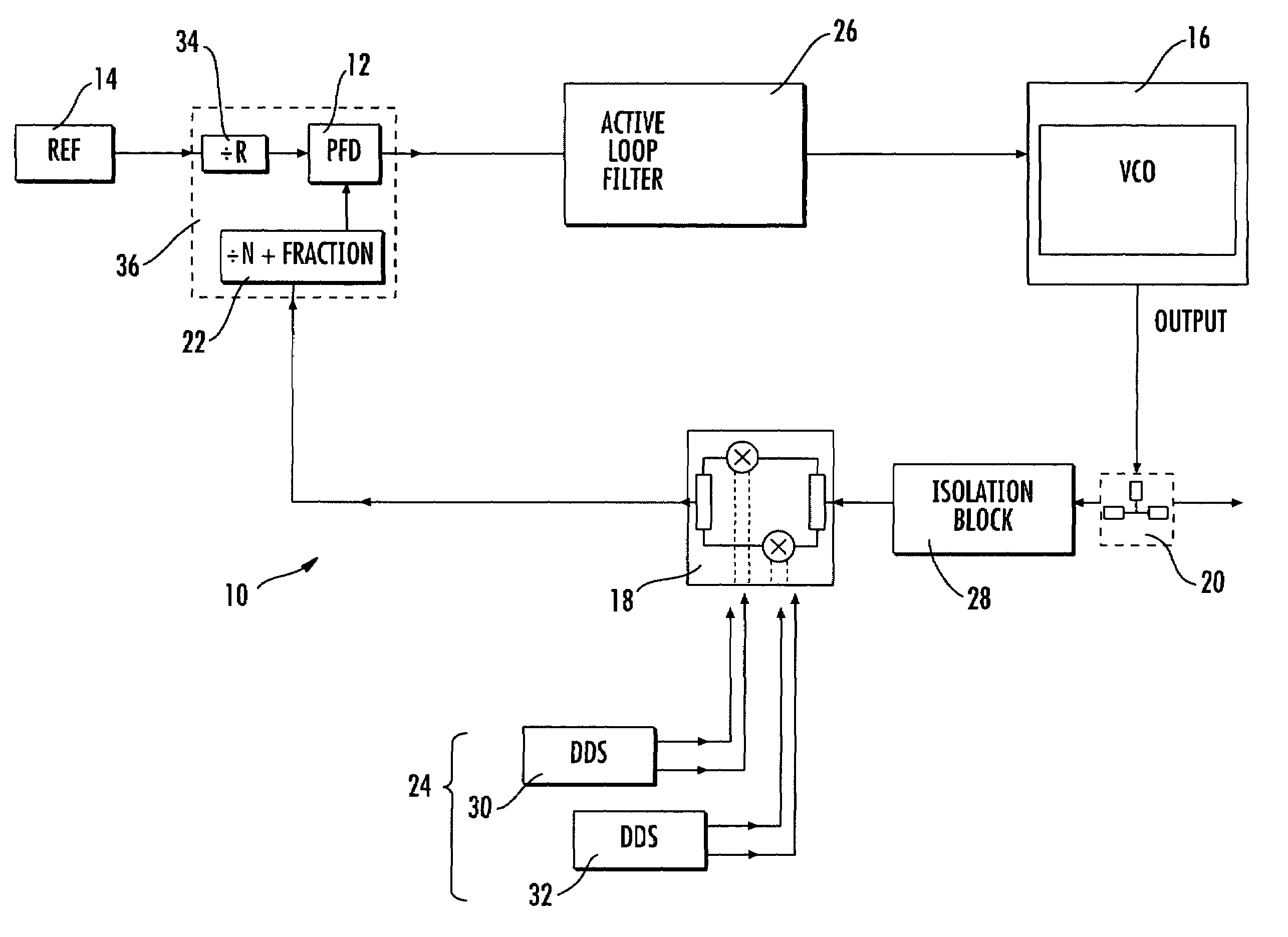
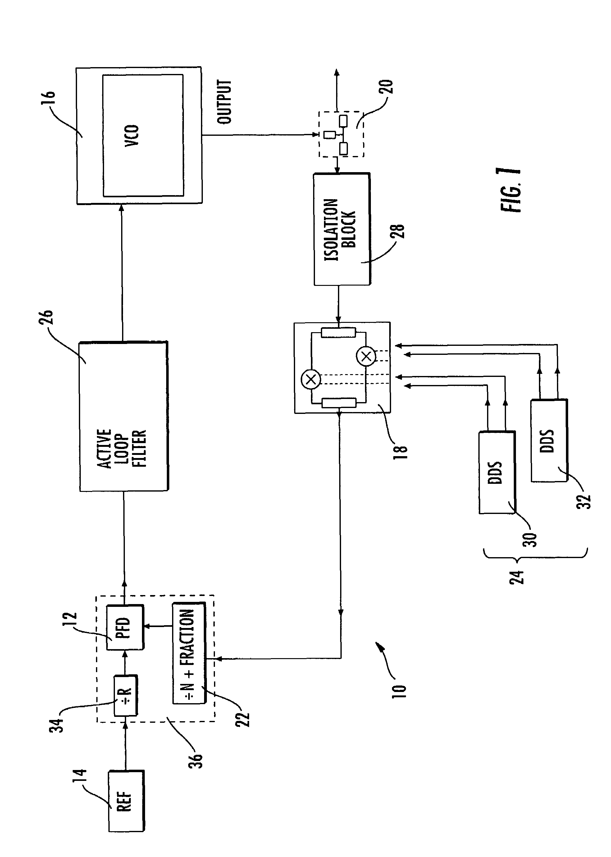
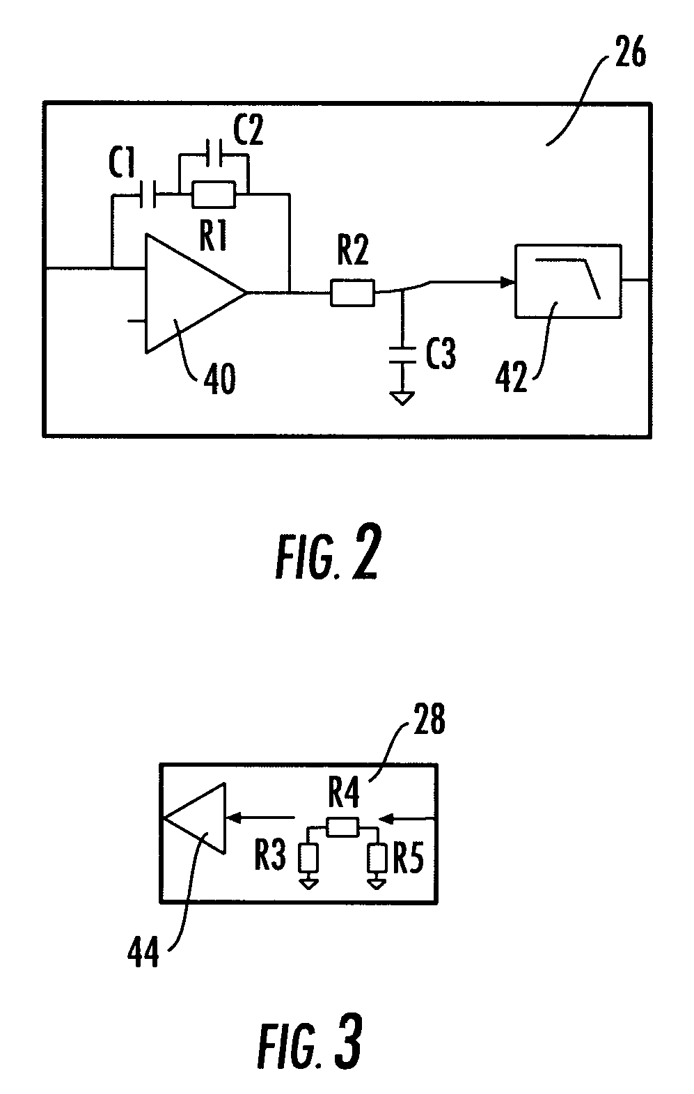
[0029]Referring initially to FIG. 1, a phase locked loop (PLL) frequency synthesizer 10 of the present invention will be described. The PLL frequency synthesizer 10 includes a phase detector 12, or phase frequency detector (PFD), receiving a reference signal, e.g. from a reference signal source 14. The phase frequency detector 12 detects both phase and frequency differences between the reference input and the feedback signal. A controlled oscillator 16 (e....


PUM


Abstract

The phase locked loop (PLL) frequency synthesizer includes a phase detector receiving a reference signal, a controlled oscillator (e.g. a voltage controlled oscillator) connected to the phase detector and generating a synthesized frequency output signal based upon the reference signal, a mixer (e.g. an in-phase and quadrature-phase (IQ) modulator) connected to the controlled oscillator, a divider connected between the mixer and the phase detector, and a signal source driving the mixer. The frequency synthesizer and method have narrow frequency steps (e.g. as low as fractions of a Hertz) while using a relatively high reference frequency to maintain low phase noise. Furthermore, the fine frequency tuning resolution is achieved while also reducing output spurs and using a relatively simple topology.

Description

FIELD OF THE INVENTION[0001]The present invention relates to the field of frequency synthesizers, and, more particularly, to frequency synthesizers with narrow frequency steps and related methods.BACKGROUND OF THE INVENTION[0002]Signal sources, sometimes referred to as frequency sources, are used to generate signals for use in many electronic systems. Applications requiring a source with both high-Q frequency stability / accuracy characteristics and frequency tunability generally require the use of a so-called “locked” signal source. In a locked source, a tunable source is locked to or otherwise derived from a fixed or “reference” source. Often the tunable source is locked to a reference source using one or more feedback circuits or feedback loops. In the case of a locked source using a feedback loop, once the feedback loop is closed the tunable source can achieve frequency stability and accuracy that are a function of the reference source frequency stability. Such a configuration of ...

Claims


Application Information

Patent Timeline
Patent Type & Authority Patents(United States)
IPC IPC(8): H03L7/00
CPCH03L7/093H03L7/1976H03L2207/12
Inventor SHIELDS, NICHOLAS PAUL
Owner HARRIS CORP
Why Eureka
Try Eureka