Object tracking system with non-contact object detection and identification

a non-contact, object technology, applied in the direction of individual entry/exit registers, mechanical actuation of burglar alarms, instruments, etc., can solve the problems of requiring precision in the placement and orientation of contact pairs, affecting requiring relatively complex and laborious fabrication, etc., to achieve the effect of less effect on the integrity and reliability of the system, less manufacturing cost, and less manufacturing cos

Inactive Publication Date: 2007-07-31
KEY CONTROL HLDG
View PDF117 Cites 74 Cited by
  • Summary
  • Abstract
  • Description
  • Claims
  • Application Information

AI Technical Summary

Problems solved by technology

Obviously, such a manual system of tracking has numerous shortcomings due in large part to the very real potential of human error and forgetfulness in carrying out the sign-in and sign-out procedures.
While the Key Track system described above has proven extremely valuable in the tracking and control of keys, it nevertheless has certain problems and shortcomings inherent in its design.
For example, the backplane of the system, which may contain dozens of upstanding metal contacts for engaging the electronic touch memory devices of key cards, can be relatively complex and labor intensive to fabricate and requires precision in the placement and orientation of contact pairs.
In addition, foreign items such as loose keys or other small metal items that may inadvertently be dropped into or hang through one of the slots in the top panel can and sometimes do short the contacts on the backplane, resulting in the potential for false key tracking logs or, in extreme cases, error conditions that can result in degradation of the integrity of the entire system.
Furthermore, because the reading of the codes stored in the touch memory devices relies upon physical contact between the touch memory devices and the electrical contacts on the backplane, resistances that can result from corroded contacts or dirty touch memory devices can also result in false and degrading readings.
Additionally, the electrical contacts sometimes become bent or sprung so that they fail to make proper contact with the touch memory devices of key cards placed in their corresponding slots.
These and other related problems all result from the requirement in the Key Track system that object detection and identification relies upon physical electrical contact between a set of electrical contacts and an electronic touch memory device.

Method used


Image

  • Object tracking system with non-contact object detection and identification
  • Object tracking system with non-contact object detection and identification
  • Object tracking system with non-contact object detection and identification

Examples


Embodiment Construction

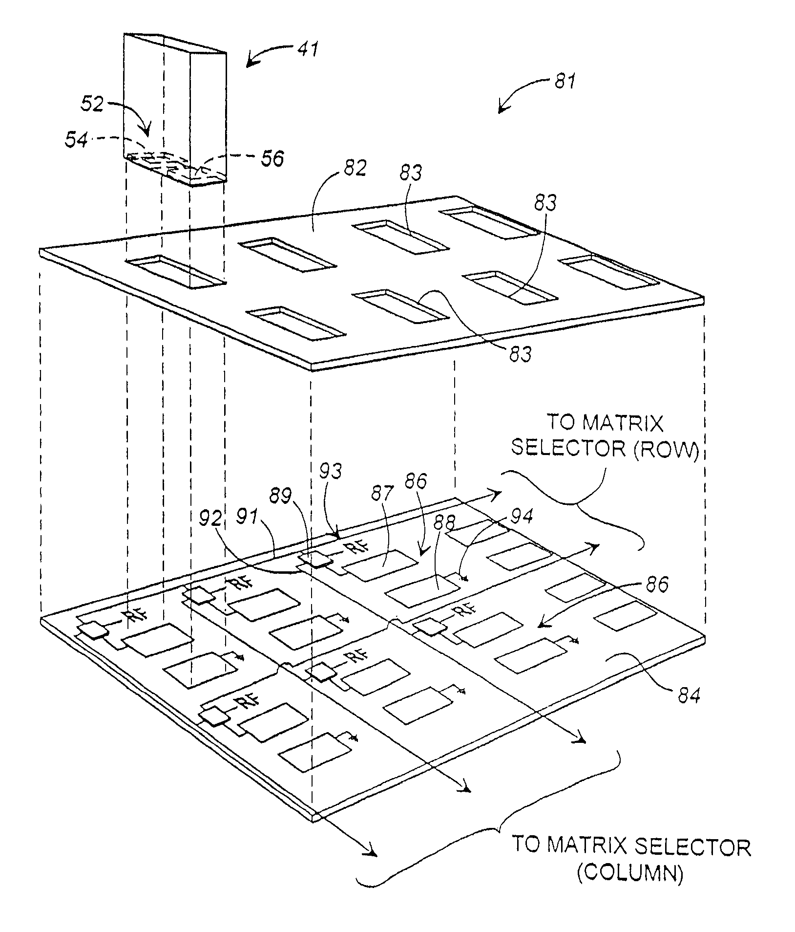
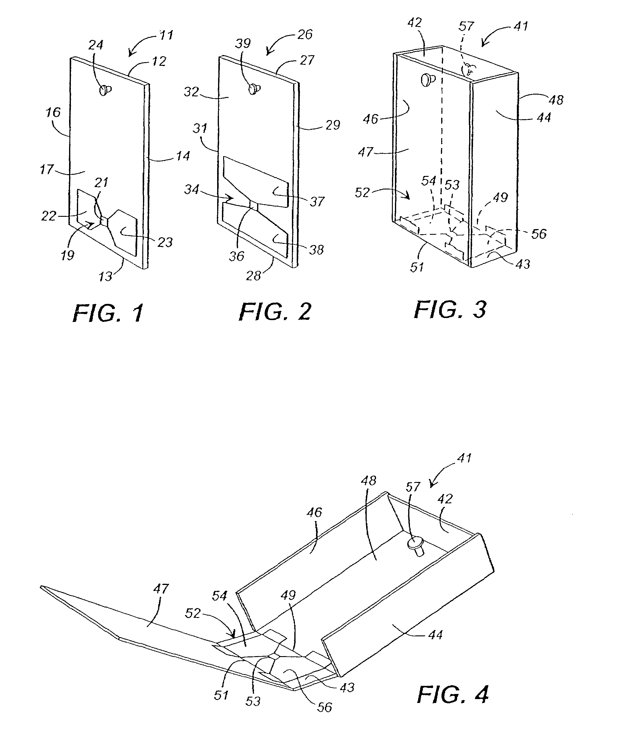
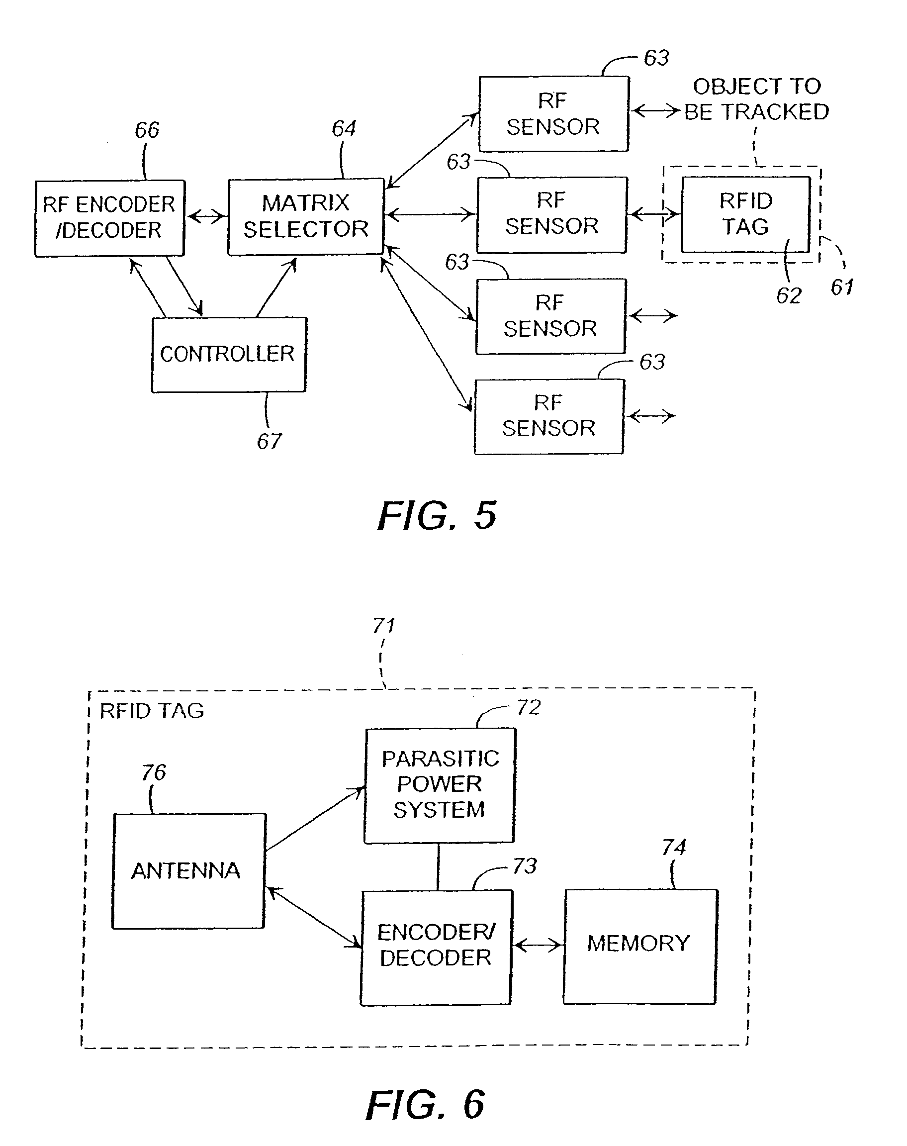
[0036]The present invention will be described in detail within the general context of a key or small item tracking system. In such a system, keys to vehicles are attached to key cards (or placed in or on the outside surface of small containers), which are checked out from and replaced in a centrally located storage unit. Each key card is provided with an RFID tag. The storage unit preferably has a top panel formed with an array of receptacles for receiving the key cards. A backplane is disposed beneath the panel and has an array of sensors for detecting and identifying key cards located in the receptacles of the storage unit. This configuration is discussed in detail in my issued patent, which provides background for the discussions that follow.

[0037]Even though a preferred embodiment of the invention is as a key or small item tracking system, it should be kept in mind during review of the detailed description that follows that the invention has a wide variety of uses wherever there...


PUM


Abstract

An object tracking system is provided for tracking the removal of objects from a location and the replacement of the objects at the location. The system includes a radio frequency identification (RFID) tag attached to each of the objects to be tracked and each tag has an antenna. When activated, the RFID tag of an object transmits a unique code identifying the object. A storage unit is provided at the location and the storage unit has a plurality of receptacles configured to receive objects replaced at the location. Each receptacle has an associated antenna for activating the RFID tag of an object in the receptacle and receiving the radio frequency transmitted code of the object. The antennae of the system can be capacitive plates for conveying the radio frequency transmissions through capacitive coupling or inductive loops for conveying the transmissions through inductive coupling. A computer-based controller is coupled to the antenna of the receptacles for receiving transmitted codes and determining based thereon the absence or presence and location of objects within the storage unit.

Description

REFERENCE TO RELATED APPLICATIONS[0001]This application is a continuation of U.S. patent application Ser. No. 10 / 614,590, filed on Jul. 7, 2003, now abandoned; which application is a continuation of U.S. patent application Ser. No. 10 / 122,507, filed on Apr. 15, 2002, now abandoned; which is a continuation of U.S. patent application Ser. No. 09 / 797,338, filed on Mar. 1, 2001, now U.S. Pat. No. 6,407,665; which is a continuation of U.S. patent application Ser. No. 09 / 393,223 filed on Sep. 9, 1999, now U.S. Pat. No. 6,204,764; which application claims the benefit of the filing date of prior filed U.S. Provisional Patent Application Ser. No. 60 / 099,954 filed Sep. 11, 1998.TECHNICAL FIELD[0002]This invention relates generally to object tracking and control systems and more particularly to systems for tracking and controlling access to and disposition of objects such as keys.BACKGROUND[0003]Many objects have intrinsic value or have value because they provide access to other valuable objec...

Claims


Application Information

Patent Timeline
Patent Type & Authority Patents(United States)
IPC IPC(8): G08B13/14G06K17/00G07B15/02G07B15/04G08B13/24
CPCG06K17/00G07B15/04G07C9/00896G08B13/1427G08B13/1454G08B13/1463G08B13/2417G08B13/2431G08B13/2434G08B13/2448G08B13/2462G08B13/2471G08B13/2474G08B13/2477G08B13/2482G08B21/023G08B21/0286G08B21/0288G06K2017/0045G07C11/00G07C2009/00936
Inventor MALONEY, WILLIAM C.
Owner KEY CONTROL HLDG
Why Eureka
Try Eureka