Method and apparatus for controlling communication within a computer network

a communication system and computer network technology, applied in data switching networks, multiplex communication, selective content distribution, etc., can solve problems such as degraded signals on such links, expensive installation of wired links, and loss of analog wireless communication links

Inactive Publication Date: 2007-07-31
CIRRUS LOGIC INC
View PDF19 Cites 54 Cited by
  • Summary
  • Abstract
  • Description
  • Claims
  • Application Information

AI Technical Summary

Benefits of technology

[0005]The present invention provides an improved scheme for wireless network communications. In particular, one embodiment of the present invention provides a method of controlling a communication channel so as to dynamically accommodate network client requests for access thereto. The communication channel may be supported on a wireless link. In such cases, allocating time slots for client transmissions on the wireless link may dynamically accommodate the client requests for access. Preferably, the communication channel is supported on a spread spectrum wireless link that supports code division multiple access (CDMA) communications. Providing a quiet time slot within which clients may request access to the communication channel may accommodate various client requests for access to the communication channel. These quiet slots may exist with other forward and reverse time slots which are superimposed on the communication channel, each forward and reverse time slot including one or more data frames.

Problems solved by technology

Such wired links are expensive to install, especially where they are added after the original construction of the home.
Although easier to install than conventional wired communication links, analog wireless communication links suffer from a number of disadvantages.
For example, degraded signals may be expected on such links because of multipath interference.
Further, interference from existing appliances, such as televisions, cellular telephones, wireless telephones and the like, may be experienced.

Method used


Image

  • Method and apparatus for controlling communication within a computer network
  • Method and apparatus for controlling communication within a computer network
  • Method and apparatus for controlling communication within a computer network

Examples


Embodiment Construction

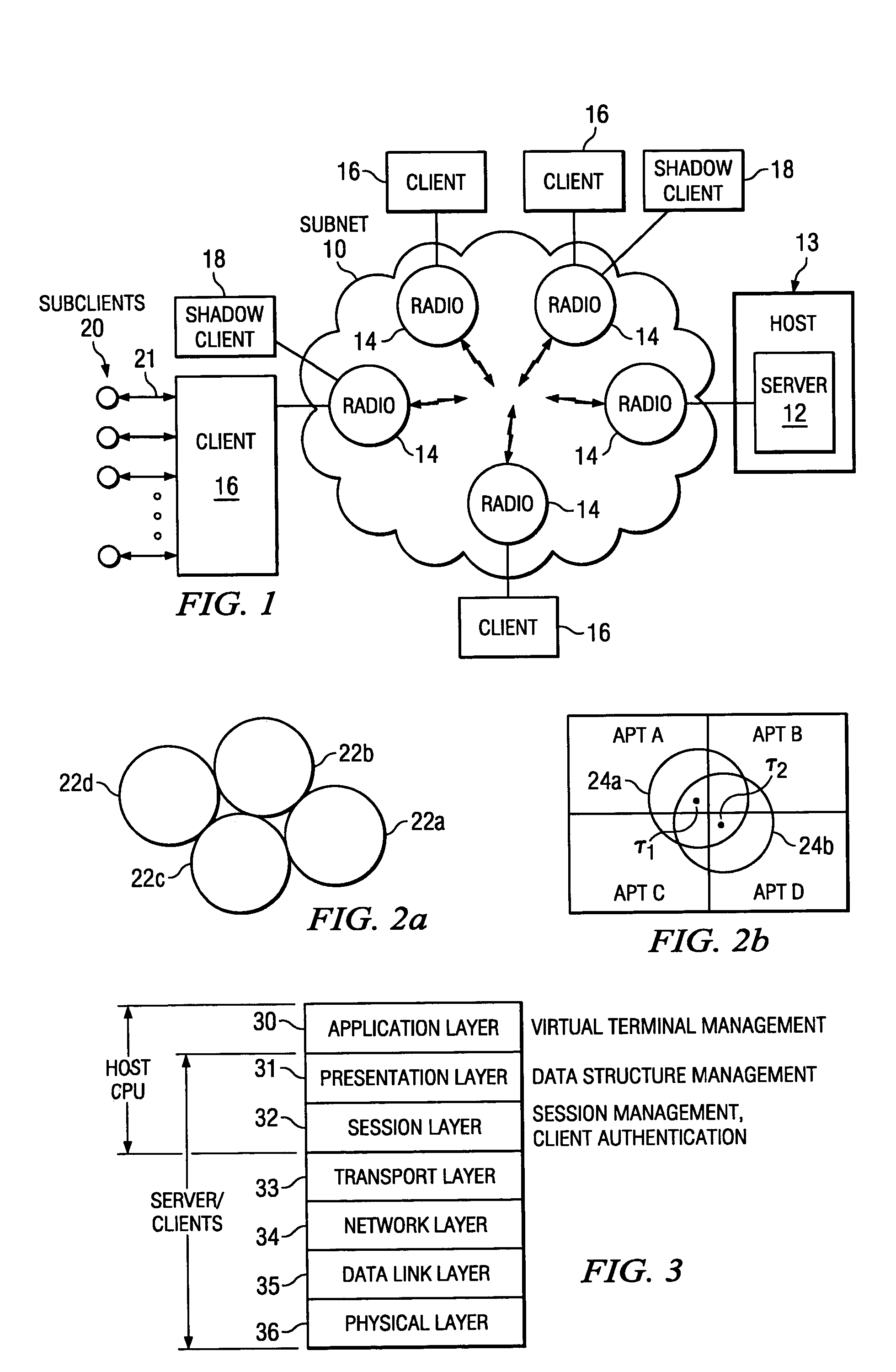
[0031]Described herein is a network architecture and related protocols for use between (a) a server and associated network clients, and (b) the server and a host computer associated therewith. The present scheme is generally applicable to a variety of wireless network environments, but finds especially useful application in a computer network which is located in a home environment. Thus, the present scheme will be discussed with reference to the particular aspects of a home environment. However, this discussion should in no way be seen to limit the applicability of the present invention to other network environments and the broader spirit and scope of the present invention is recited in the claims which follow this discussion.

[0032]As used herein, a “subnet” may describe a cluster of network components which includes a server and several clients associated therewith (e.g., coupled through a wireless communication link). Depending on the context of the discussion, a subnet may also r...


PUM


Abstract

A communication channel is controlled so as to dynamically accommodate network client requests for access thereto. The communication channel may be supported on a wireless link, such as a spread spectrum wireless link, and client requests for access thereto may be dynamically accommodated by allocating time slots for client transmissions on the wireless link. Providing a quiet time slot within which clients may request access to the communication channel may accommodate various client requests for access to the communication channel. These quiet slots may exist with other forward and reverse time slots which are superimposed on the communication channel, each forward and reverse time slot including one or more data frames. The forward and reverse time slots are preferably fixed, but negotiable, time periods. Each of the data frames may include a plurality of data packets, each of the data packets being variable in length. Preferably, each of the data packets includes error correction coding information as well as information which may be used to synchronize pseudo-random number generators of a transmitter and a receiver operating according to the communication protocol. Each of the data frames may further include link identification information that uniquely identifies a wireless link supporting the communication protocol.

Description

FIELD OF THE INVENTION[0001]The present invention relates generally to a scheme for communications within a computer network and, in particular, to such communications as occur between a central server and a number of client units across a wireless link.BACKGROUND[0002]Modern computer networks allow for inter-communication between a number of nodes such as personal computers, workstations, peripheral units and the like. Network links transport information between these nodes, which may sometimes be separated by large distances. However, to date most computer networks have relied on wired links to transport this information. Where wireless links are used, they have typically been components of a very large network, such as a wide area network, which may employ satellite communication links to interconnect network nodes separated by very large distances. In such cases, the transmission protocols used across the wireless links have generally been established by the service entities car...

Claims


Application Information

Patent Timeline
Patent Type & Authority Patents(United States)
IPC IPC(8): H04J3/00H04L12/28H04L12/403H04L12/56H04L29/06H04N21/436H04N21/4363H04W28/04H04W72/04H04W74/00H04W74/04H04W74/08
CPCH04L12/403H04L29/06H04N21/43615H04N21/43637H04W28/16H04L12/2803H04L12/2816H04L29/06027H04L2012/2841H04L2012/2849H04W28/04H04W84/02H04L67/42H04L67/01H04L9/40H04L67/2866H04L65/1101
Inventor GUBBI, RAJUGOPAL
Owner CIRRUS LOGIC INC
Why Eureka
Try Eureka