
Integrated gearless and nonlubricated auxiliary power unit

a technology of auxiliary power units and gearless lubrication, which is applied in the direction of machines/engines, efficient propulsion technologies, light and heating apparatus, etc., can solve the problems of increasing the overall size and weight of the apu, the main engine may not be operating, and the main engine may not be able to supply power

Active Publication Date: 2007-08-07
HONEYWELL INT INC
View PDF31 Cites 56 Cited by
  • Summary
  • Abstract
  • Description
  • Claims
  • Application Information

AI Technical Summary

Benefits of technology

The present invention provides an integrated auxiliary power unit (APU) that does not use gears between the turbine and other rotating components and does not require a flow of lubricant. The APU includes a combustor, turbine, compressor, starter-generator unit, and quill shaft assembly. The compressor has foil bearings that support the turbine, and the quill shaft assembly connects the turbine output shaft to the motor / generator rotor. The APU can operate in either a motor mode or a generator mode, and a control unit can selectively configure the motor / generator to operate in either mode. The invention provides a more efficient and compact APU design.

Problems solved by technology

However, when an aircraft is on the ground, its main engines may not be operating.
Moreover, in some instances the main engines may not be capable of supplying power.
This can increase the overall size and weight of the APU.
However, such APU configurations may also suffer certain drawbacks.
For example, extensive design and high manufacturing tolerances may be needed to avoid unwanted shaft vibrations, which can increase overall costs.
Moreover, such APUs have thus far been implemented using multi-stage compressors and / or turbines, which can increase the overall size, weight, and cost of the APU.
Many APUs may also include starter-generator control units that are disposed external to the APU, and thus occupy space within the aircraft fuselage.
Thus, the APU may be designed and implemented to include one or more interfaces to external lubrication systems, which can increase overall size, weight, and cost.

Method used


Image

  • Integrated gearless and nonlubricated auxiliary power unit
  • Integrated gearless and nonlubricated auxiliary power unit
  • Integrated gearless and nonlubricated auxiliary power unit

Examples


Embodiment Construction

[0025]Before proceeding with a detailed description, it is to be appreciated that the described embodiment is not limited to use in conjunction with a particular type of turbine engine. Thus, although the present embodiment is, for convenience of explanation, depicted and described as being implemented as an auxiliary power unit, it will be appreciated that it can be implemented as various other types of devices, and in various other systems and environments.

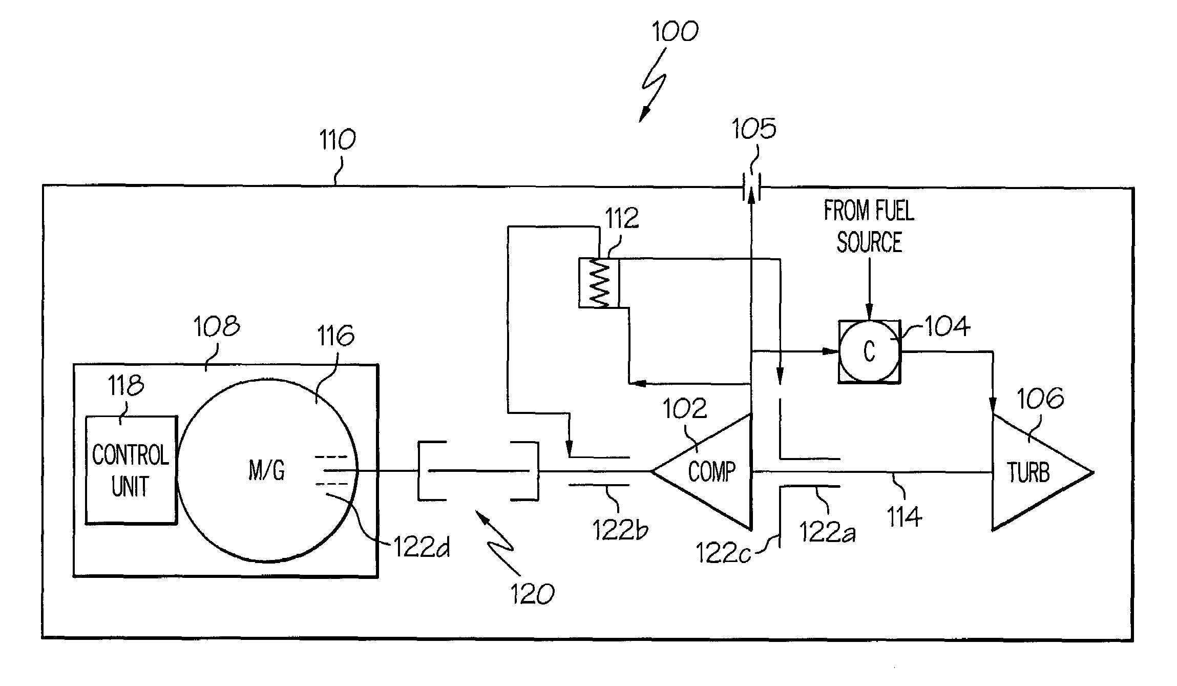
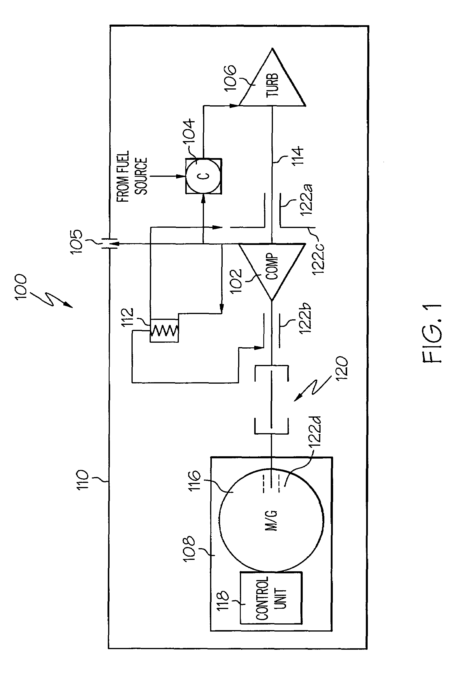
[0026]Turning now to the description, and with reference first to FIG. 1, an embodiment of an exemplary auxiliary power unit (APU) 100 is shown in simplified schematic form. The APU 100 includes a compressor 102, a combustor 104, a turbine 106, and a starter-generator unit 108, all preferably housed within a single containment housing 110. During operation of the APU 100, the compressor 102 draws ambient air into the containment housing 110. As will be described more fully below, in a particular preferred embodiment, the ambient...


PUM


Abstract

An auxiliary power unit (APU) includes a compressor, a turbine, a combustor, and a starter-generator unit all integrated within a single containment housing. The turbine has an output shaft on which the compressor is mounted, and the starter-generator unit is coupled to the turbine output shaft without any intervening gears. The rotating components are all rotationally supported within the containment housing using bearings that do not receive a flow of lubricating fluid.

Description

TECHNICAL FIELD[0001]The present invention relates to gas turbine engines and, more particularly, a gas turbine engine auxiliary power unit that is non-lubricated and includes integrated electrical power and electronics.BACKGROUND[0002]Aircraft main engines not only provide propulsion for the aircraft, but in many instances may also be used to drive various other rotating components such as, for example, generators, compressors, and pumps, to thereby supply electrical, pneumatic, and / or hydraulic power. However, when an aircraft is on the ground, its main engines may not be operating. Moreover, in some instances the main engines may not be capable of supplying power. Thus, many aircraft include one or more auxiliary power units (APUs) to supplement the main propulsion engines in providing electrical and / or pneumatic power. An APU may additionally be used to start the main propulsion engines.[0003]An APU is, in most instances, a gas turbine engine that includes a combustor, a power t...

Claims


Application Information

Patent Timeline
Patent Type & Authority Patents(United States)
IPC IPC(8): F02C7/06F02C7/18F02C7/275B64D41/00F01D15/10F02C3/09F02C7/32F23R3/06H02K7/18
CPCB64D41/00F01D15/10F02C3/09F02C7/32F23R3/06H02K7/1823Y02T50/675F05D2240/50F05D2220/50Y02T50/60
Inventor DITTMAR, KEVIN S.EDMONDS, DAVID H.SCHENK, BJOERNSHEORAN, YOGENDRA Y.
Owner HONEYWELL INT INC
Learn More