Cylinder apparatus

a technology of cylinders and cylinder bodies, applied in the direction of shock absorbers, power plant inspection panels, machines/engines, etc., can solve the problems of shock absorbers provided, shock absorbers may be damaged, and strange noises may aris

Active Publication Date: 2007-08-07
HITACHI ASTEMO LTD
View PDF7 Cites 13 Cited by
  • Summary
  • Abstract
  • Description
  • Claims
  • Application Information

AI Technical Summary

Benefits of technology

[0007]In order to solve the above described problem, there is provided according to the invention a cylinder apparatus comprising a cylinder, a piston which is slidably inserted into the cylinder, and a piston rod which is connected to the piston at one end of the rod and extended outside of the cylinder at the other end, wherein the cylinder apparatus further includes in the cylinder a rebound spring having at one end a spring holder which is slidably guided along the piston rod, and whose other end is fixed to the piston so as to be compressed by an extending stroke of the piston rod, and a stopper unit which is fixed to the piston rod apart from the piston at a position between the spring holder and the piston, and adapted to come into contact with the spring holder before the rebound spring has arrived at the maximum compressed state, thereby preventing further compression of the rebound spring.
[0009]On this occasion, a repulsive force of the rebound spring when the rebound spring is compressed will be received by the piston to which the rebound spring is connected, while the force for preventing the compression of the rebound spring beyond the determined amount will be received by the stopper unit which is separated from the piston. Therefore, the force generated when the cylinder apparatus is in the maximum extended state can be dispersed.

Problems solved by technology

However, the conventional hydraulic shock absorber provided with the rebound spring as described above has had the following problem.
As a result, strange noises may arise, and the rebound spring may be damaged.

Method used


Image

  • Cylinder apparatus
  • Cylinder apparatus

Examples


Embodiment Construction

[0012]Now, an embodiment of the present invention will be described in detail referring to the drawing.

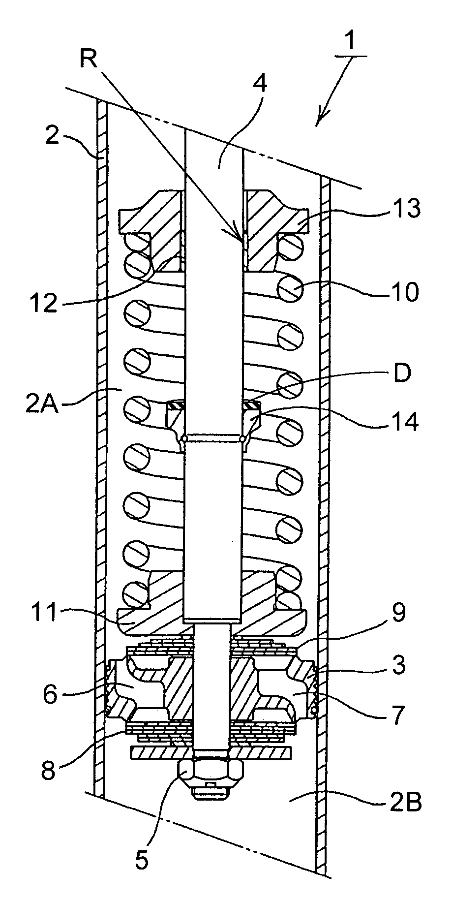
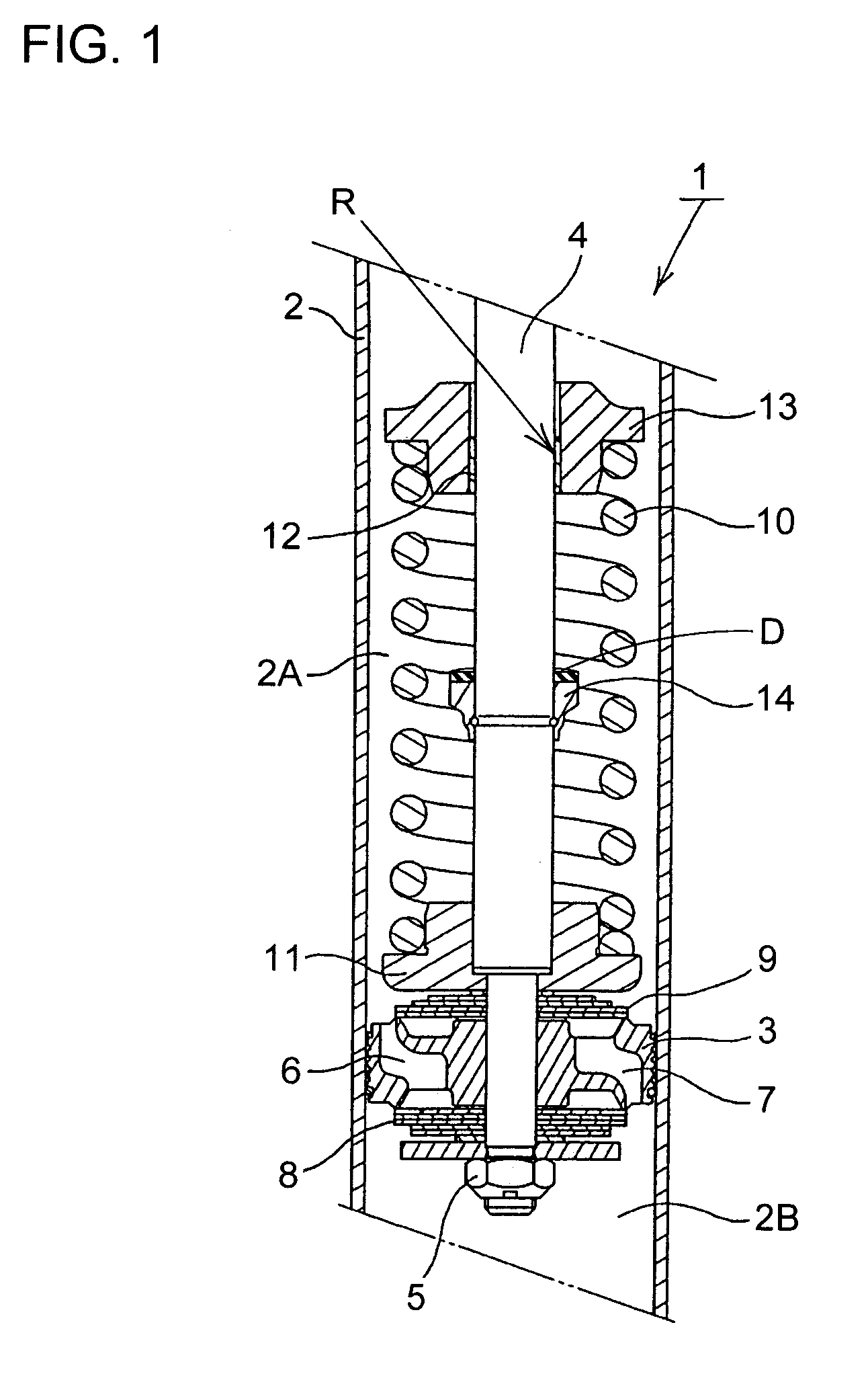
[0013]Referring to FIG. 1, the embodiment of the invention will be described. As shown in FIG. 1, the hydraulic shock absorber 1 according to the embodiment of the invention is a single cylinder hydraulic shock absorber to be mounted on a suspension system in an automobile, and includes a cylinder 2 in which liquid oil is contained, and a piston 3 which is slidably inserted into the cylinder 2. The interior of the cylinder 2 is divided by this piston 3 into two chambers, namely, an upper cylinder chamber 2A and a lower cylinder chamber 2B. One end of a piston rod 4 is connected to the piston 3 by means of a nut 5, while the other end of the piston rod 4 is passed through a rod guide (not shown) and an oil seal (not shown) which are attached to an upper end part of the cylinder 2, and extended to the outside. A free piston (not shown) is slidably provided in a lower end part of the ...


PUM


Abstract

In a cylinder apparatus such as a hydraulic shock absorber, a piston to which a piston rod is connected slidably is inserted into a cylinder which contains liquid oil. A rebound spring is wound around the piston rod with one end of the piston rod fixed to the piston rod using a spring holder. The rebound spring is slidably guided along the piston rod by means of another spring holder. A rebound stopper is fixed to the piston rod at a position between the spring holders. The rebound spring exerts a spring force opposite to the extension of the piston rod, thereby to moderate shock at the end of the stroke of the piston. Because the spring holder comes into contact with the rebound stopper, contact of adjacent linear portions of the rebound spring with each other due to excessive compression of the rebound spring can be prevented, and also occurrence of strange noise and damage of the rebound spring can be prevented.

Description

BACKGROUND OF THE INVENTION[0001]1. Field of the Invention[0002]The present invention relates to a cylinder apparatus in which a piston having a piston rod connected thereto is slidably inserted into a cylinder, such as a hydraulic shock absorber, a gas spring, and so on.[0003]2. Description of Related Art[0004]As an example of a hydraulic shock absorber to be mounted in a suspension system of a vehicle such as an automobile, there has been the type disclosed in JP-A-6-101734, in which a rebound spring (a helical compression spring) is wound around a piston rod connected to a piston which is slidably inserted into a cylinder. In this hydraulic shock absorber, when the piston rod has been extended up to a position near its maximum extendable position, the rebound spring is compressed and exerts a spring force against further extension of the piston rod so that it is difficult for the piston rod to arrive at the end of its stroke, and thus the shock at end of the stroke is moderated.[...

Claims


Application Information

Patent Timeline
Patent Type & Authority Patents(United States)
IPC IPC(8): F01B11/02F16F9/58
CPCF16F9/585
Inventor NAKAMURA, HIROSHITOTANI, YOSHIAKI
Owner HITACHI ASTEMO LTD
Why Eureka
Try Eureka