Quartz resonator of small dimensions

a resonator and small dimension technology, applied in piezoelectric/electrostrictive/magnetostrictive devices, electrical apparatus, impedence networks, etc., can solve the problems of mechanical structure and still too large piezoelectric generators, and achieve the effect of reducing the total size of resonators and strengthening lateral shock resistan

Active Publication Date: 2007-08-07
ETA SA MFG HORLOGERE SUISSE
View PDF11 Cites 38 Cited by
  • Summary
  • Abstract
  • Description
  • Claims
  • Application Information

AI Technical Summary

Benefits of technology

[0010]Within the scope of the present invention, it has been demonstrated that replacing the notches formed in the base by a hole made in the fixing zone of the resonator and the vibrating arms allows the static thermal stresses to be perfectly uncoupled from the median zone of the base located between the arms, and thus to have no coupling in the dynamic elastic stress zone. This hole also allows the effective length of the arms to be artificially elongated, thus reducing the total size of the resonator for the same resonance frequency. Moreover, lateral shock resistance is reinforced, since the resonator no longer has a weak point in proximity to the fixing zone, while maintaining the same resistance as a solution with notches in the direction perpendicular to the resonator plane.
[0012]This type of resonator is generally intended to be packaged in a case. Owing to the advantages obtained by the use of a hole instead of notches, it is possible to further improve shock resistance by selecting a rigid mounting, like for example an epoxy conductive adhesive, for fixing the resonator to its case.
[0013]It will also be noted, again for the purpose of improving the resistance of the resonator, that the hole advantageously has a polygonal shape the sides of which are cut so as to minimise visualization of the crystalline planes of the piezoelectric resonator.

Problems solved by technology

Although of small dimensions, of the order of a millimeter, such piezoelectric generators are still too bulky in light of the ever increasing demand for miniaturisation of electronic equipment, such as portable telephones or watches.
However, such a solutions has certain drawbacks.
Nonetheless, such flexible adhesive agents exhibit problems of adherence and resistance to shocks, such a solution is thus undesirable.
Moreover, notches 5a and 5b weaken the mechanical structure of resonator 1, which raises a problem in the event of shocks, and more specifically in the event of lateral shocks.

Method used


Image

  • Quartz resonator of small dimensions
  • Quartz resonator of small dimensions
  • Quartz resonator of small dimensions

Examples


Embodiment Construction

[0024]As previously mentioned, the present invention concerns a piezoelectric resonator having, on the one hand, reduced power consumption owing to excitation by a more homogenous electrical field and, on the other hand, proper mechanical uncoupling between the base and the arms of the resonator as well as greater shock resistance, particularly to lateral shocks.

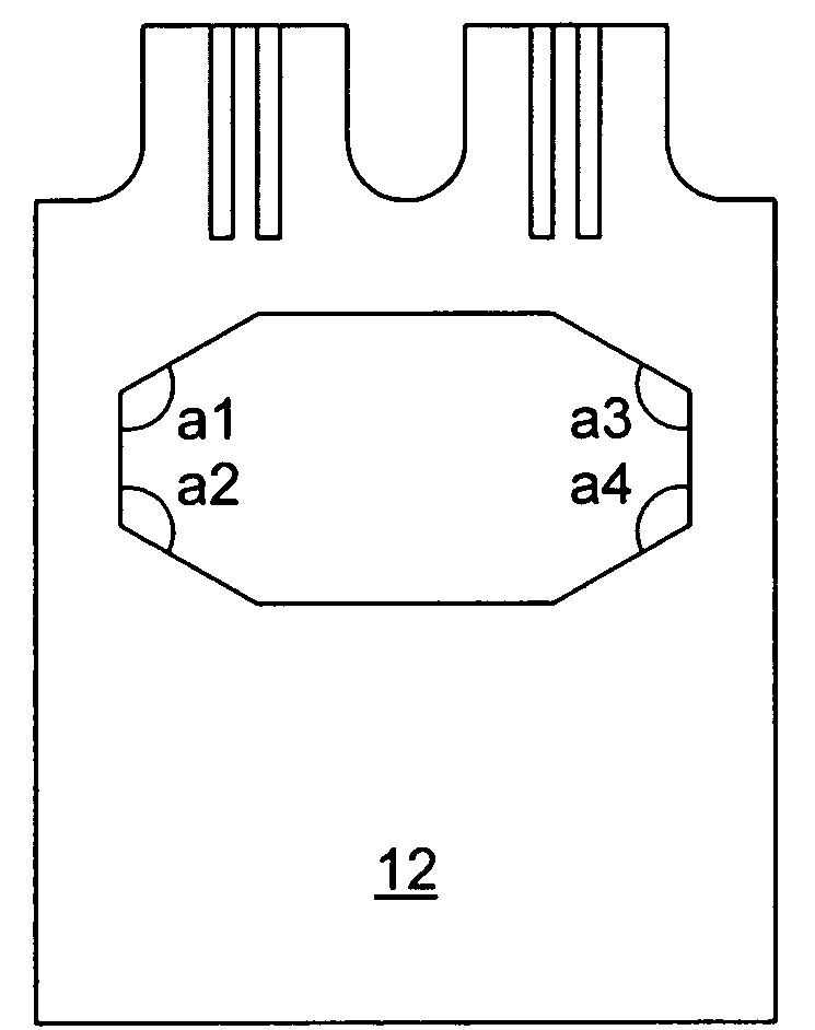
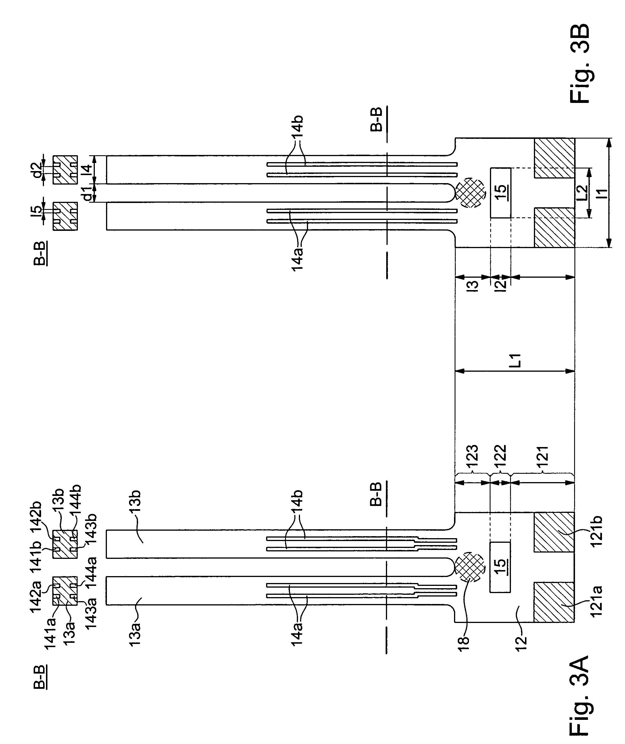
[0025]FIGS. 3A and 3B show a tuning fork piezoelectric resonator according to two variants of a first embodiment of the invention. Resonator 10 includes a base 12 from which extends two vibrating arms 13a and 13b each having at least one groove 14a, 14b on at least one of the top and / or bottom faces of the arms. In the example shown, along the cross-section B-B, each of arms 13a and 13b advantageously includes two grooves (141a-144a, 141b, 144b) on each of the top and bottom faces.

[0026]The use of two small grooves optimises the piezoelectric coupling while maximising the dynamic capacity of the resonator and reducing to a m...


PUM


Abstract

The invention concerns a piezoelectric resonator (10), intended to be packaged in a case, including a base (12) formed of a first fixing zone (121), a second central mechanical uncoupling zone (122) and a third zone (123) opposite to the first fixing zone. At least two vibrating arms (13a, 13b) extend from said third zone, on each of which at least one groove (141a-144a, 141b-144b) is formed on at least one of the top or bottom faces of the arms. The resonator is characterised in that the base is provided with a hole (15) through the second central mechanical uncoupling zone.

Description

[0001]This application claims priority from European Patent Application No. EP 04104267.2 filed 3 Sep. 2004, the entire disclosure of which is incorporated herein by reference.FIELD OF THE INVENTION[0002]The present invention concerns, generally, piezoelectric resonators and more specifically, resonators of very small dimensions, which are usually used for making frequency generators, particularly for portable electronic equipment, in numerous fields, such as watchmaking, information technology, telecommunications and medicine.BACKGROUND TO THE INVENTION[0003]Tuning fork piezoelectric resonators are known in which the electrical excitation field is created in a direction parallel to one of their faces by electrodes, some of which are arranged on said face. Such a tuning fork resonator 1, shown in FIG. 1, includes a base 2 and two vibrating arms 3a and 3b extending from the base. With a view to reducing energy consumption owing to excitation by a more homogenous electrical field, the...

Claims


Application Information

Patent Timeline
Patent Type & Authority Patents(United States)
IPC IPC(8): H03H9/215H03H9/21
CPCH03H9/02133H03H9/215
Inventor DALLA PIAZZA, SILVIOLUTHI, THOMASSTUDER, BRUNO
Owner ETA SA MFG HORLOGERE SUISSE
Why Eureka
Try Eureka