Leak detecting device

a detection device and leak detection technology, applied in the direction of measurement devices, instruments, structural/machine measurement, etc., can solve the problems of reducing the suction capacity, the internal pressure is so high that the mass spectrometer cannot work, etc., and achieve the effect of increasing the sensitivity

Active Publication Date: 2007-08-14
INFICON GMBH
View PDF5 Cites 4 Cited by
  • Summary
  • Abstract
  • Description
  • Claims
  • Application Information

AI Technical Summary

Benefits of technology

[0003]It is an object of the invention to provide an inexpensive leak detecting device having an improved suction capacity.
[0005]The leak detecting device according to the invention comprises a second valve in the course of the connecting conduit, which is arranged parallel to the adjustable first valve. By the second valve, the overall conductance of all opened valves in the course of the connecting conduit is considerably increased so that a good overall conductance can also be realized with relatively inexpensive valves with a small inner diameter. Thus, the need of a very expensive single valve with a large inner diameter, i.e., with a high conductance, can be avoided. Both valves are arranged parallel to each other, i.e., they are parallel to each other in the course of the only connecting conduit between the leak detecting device input and the only intermediate inlet of the high vacuum pump.
[0007]In oil-sealed prevacuum pumps, the leak detecting device input is evacuated to about 1 mbar, and when the pressure decreases below this value, the adjustable first valve is opened first, and later on, the second valve in the course of the connecting conduit is opened. Thereby, a sensitive measurement is made possible at an early time. From a pressure of 10−2 mbar up, both parallel valves can be fully opened to provide a suction capacity at the leak detecting device input, which is as great as possible.
[0008]By providing a second valve parallel to the first adjustable valve, a high conductance is obtained when the valves are open, whereby valves with a relatively small diameter or cross-section may be used, which are available at low costs.
[0009]According to one version of the invention, the second valve is a switch valve that can be switched between an open and a closed condition. The second valve serves to increase the conductance of the overall valve arrangement. Thus, there is no need for an adjustable valve for the second valve and an inexpensive switch valve may be used.
[0011]According to one version of the invention, the inner diameter of each of the first and the second valves is smaller than 13 mm. Valves with an inner diameter of less than 13 mm are relatively inexpensive so that the overall valve arrangement in the connecting conduit can thus be realized in a more inexpensive manner than in the form of a single valve with a correspondingly large inner diameter.

Problems solved by technology

The adjustable valve serves as an adjustable throttle while the pressure at the leak detecting device input is so high that an unthrottled connecting conduit in the mass spectrometer would lead to an internal pressure that is so high that the mass spectrometer does not work.
Thereby, however, a considerable throttle effect is maintained, reducing the suction capacity, even if the valve is completely open.

Method used


Image

  • Leak detecting device
  • Leak detecting device

Examples


Embodiment Construction

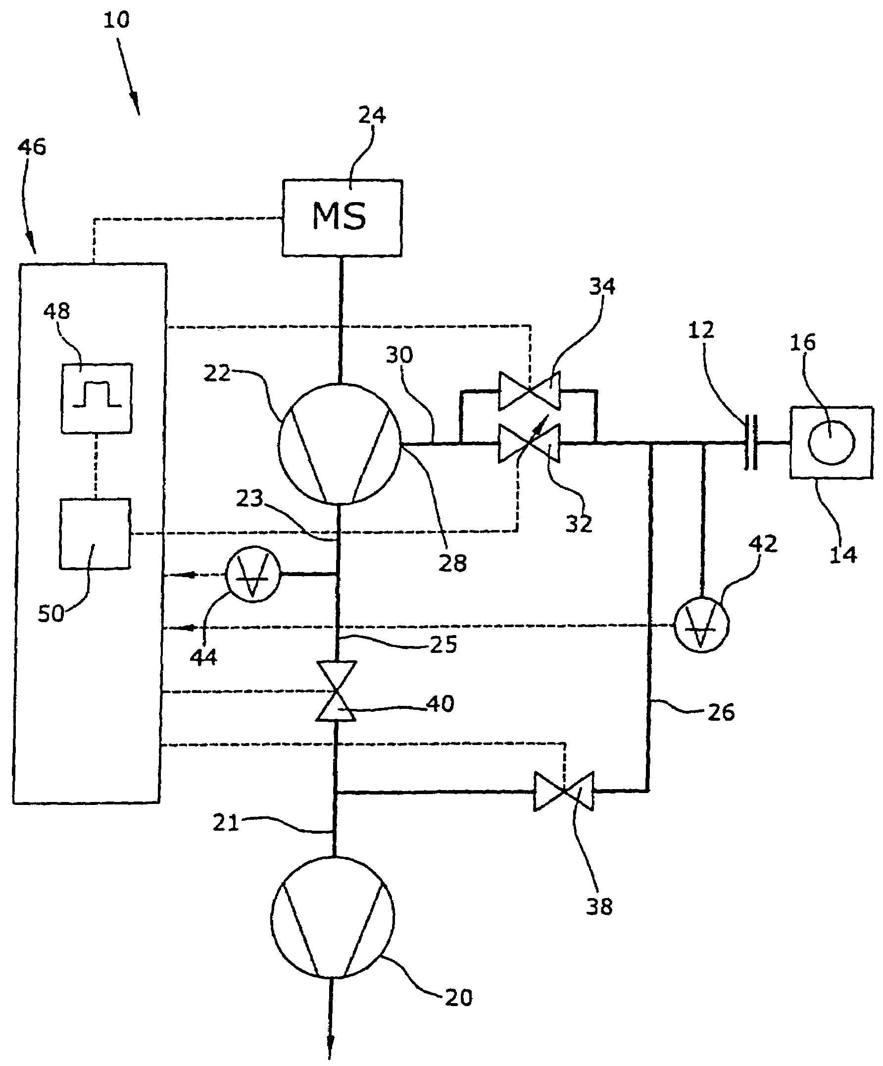
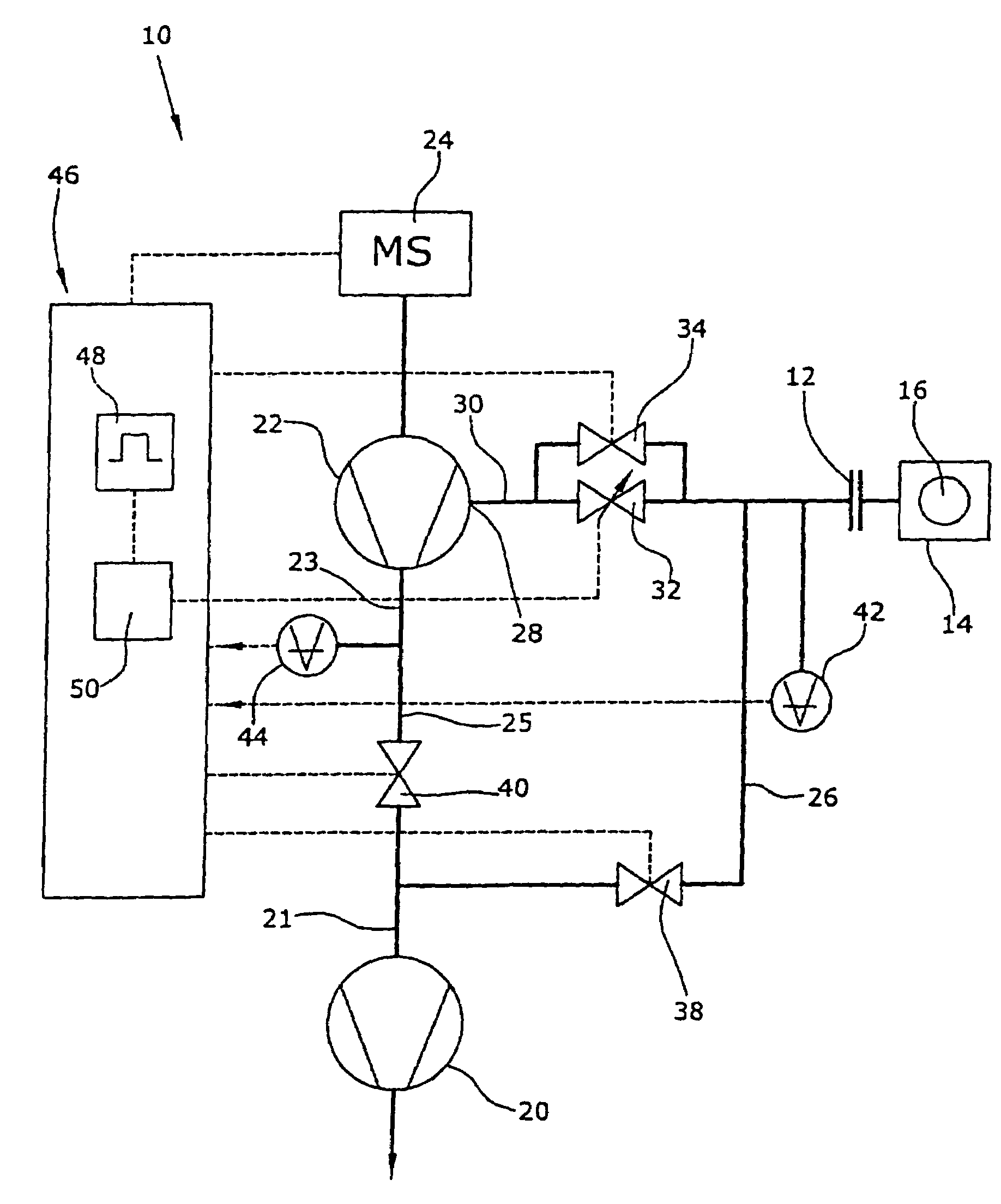
[0015]In the FIGURE, a leak detecting device 10 is illustrated which comprises a leak detecting device input 12 to which a test chamber 14 with a test sample 16 is connected. The test sample 16 contains a test gas, e.g., helium, of which even small amounts are detected by the leak detecting device 10.

[0016]The leak detecting device 10 is substantially formed by a prevacuum pump 20, a high vacuum pump 22 and a mass spectrometer 24 which are interconnected by gas lines in this order. Further, a bypass line 26 is provided between the leak detecting device input 12 and an inlet 21 of the prevacuum pump 20, and a connecting conduit 30 is provided between the leak detecting device input 12 and an intermediate inlet 28 of the high vacuum pump 22. In the course of the connecting conduit 30, two valves are arranged, namely a first valve 32 that is continuously adjustable with respect to its conductance and parallel thereto a second valve 34 that is configured as a switch valve. In the course...


PUM


Abstract

A leak detecting device of the counterflow type includes a high vacuum pump having an inlet connected to a mass spectrometer. In addition, a prevacuum pump is provided having an inlet connected to an outlet of the high vacuum pump and a leak detecting device input. A connecting conduit is further provided between the leak detecting device input and an intermediate inlet of the high vacuum pump. A first valve of variable conductance is arranged in the course of the connecting conduit. Valves with a large inner diameter are expensive while valves with a small inner diameter show considerable resistance even in a fully opened state. A second valve arranged parallel to the first adjustable valve is provided in the course of the connecting conduit; thereby allowing the first and second valves to have relatively small inner diameters arranged in the connecting conduit, wherein the combined conductance of both opened valves is considerably increased.

Description

FIELD OF THE INVENTION[0001]The invention relates to a leak detecting device working according to the counterflow type.BACKGROUND OF THE INVENTION[0002]Such a leak detecting device is known from WO 96 / 24828. In a leak detecting device of this type, the sensitivity and the detection limit of the leak detecting device can be respectively adjusted. To this end, the high vacuum pump the inlet of which is connected with a mass spectrometer and the outlet of which is connected with a prevacuum pump is provided with an intermediate inlet which is connected to the leak detecting device input via a connecting conduit. In the course of the connecting conduit, a valve of adjustable conductance is provided. The adjustable valve serves as an adjustable throttle while the pressure at the leak detecting device input is so high that an unthrottled connecting conduit in the mass spectrometer would lead to an internal pressure that is so high that the mass spectrometer does not work. For reasons of c...

Claims


Application Information

Patent Timeline
Patent Type & Authority Patents(United States)
IPC IPC(8): G01M3/04G01M3/20
CPCG01M3/202
Inventor BOHM, THOMASGROSSE BLEY, WERNER
Owner INFICON GMBH
Why Eureka
Try Eureka