
Multifunctional sprinkler structure

Active Publication Date: 2007-08-14
YUAN MEI CORP
View PDF14 Cites 40 Cited by
  • Summary
  • Abstract
  • Description
  • Claims
  • Application Information

AI Technical Summary

Benefits of technology

[0003]It is, therefore, the primary purpose of the present invention to provide a multifunctional sprinkler structure, comprising a water motor having an outlet seat and a top cover mounted to a top-end side, and two adjusting seats and a water supply seat assembled onto a bottom-end side wherein barriers of the outlet seat and water-guiding ribs of a spray nozzle are utilized to correspond to the direction of water flow. When the water flow propels an impeller to rotate towards the direction of the barriers, the impetus of the water flow hindered by the barriers will become weakened. And when the water flow enters the spray nozzle, the water flow will run in a direction counter to that of the water-guiding ribs and further hindered thereby. Thus, the water flow will concentrate in the center of the spray nozzle to emit outwards in more direct and forceful column-like spray. However, when the water flow propels the impeller to spin towards the other side thereof, the water flow released from the hindrance of the barriers will flush directly towards the spray nozzle. Then, the water flow will run in a direction identical to that of the water-guiding ribs, and the water flow guided by the ribs will keep augmenting its impetus to eject in a radial direction outwards in more expanding spray thereby.
[0004]It is, therefore, the second purpose of the present invention to provide a multifunctional sprinkler structure wherein a switch shaft is applied to locate at one side of a sliding groove of a linking piece therein, which presets an appropriate space and allows the water motor to keep rotating till the switch shaft swinging from one side of the sliding groove to the other side thereof and pressed thereby so as to switch the direction of the water flow. Therefore, the sprinkler can operate accurately to achieve precise back-and-forth swing in 360 degrees so that the water discharge can be evenly distributed to sprinkle onto the lawn.
[0005]It is, therefore, the third purpose of the present invention to provide a multifunctional sprinkler structure wherein the top cover has an assembling groove for the engagement of a control piece therewith, and the control piece can be movable slid outwards to extend above the spray nozzle and hinder the water flow ejecting outwards in low parabola spray. Otherwise, the control piece is retrieved to locate at the assembling groove therein, permitting the water flow released from the hindrance thereof to emit outwards in high parabola spray. Thus, the sprinkler can be easily adjusted to switch the height of the water discharge sprinkling onto the lawn in either farther or nearer range, achieving more flexible application of the sprinkler and boosting its functions thereof.

Problems solved by technology

When the water flow propels an impeller to rotate towards the direction of the barriers, the impetus of the water flow hindered by the barriers will become weakened.

Method used


Image

  • Multifunctional sprinkler structure
  • Multifunctional sprinkler structure
  • Multifunctional sprinkler structure

Examples


Embodiment Construction

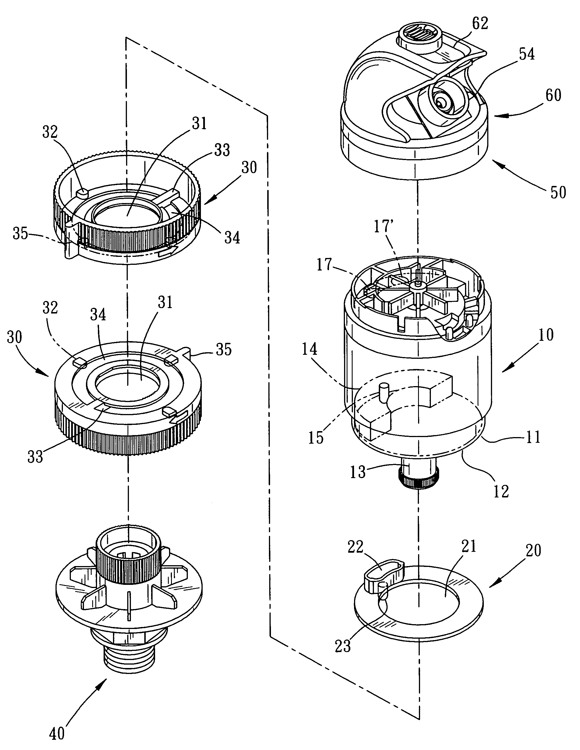
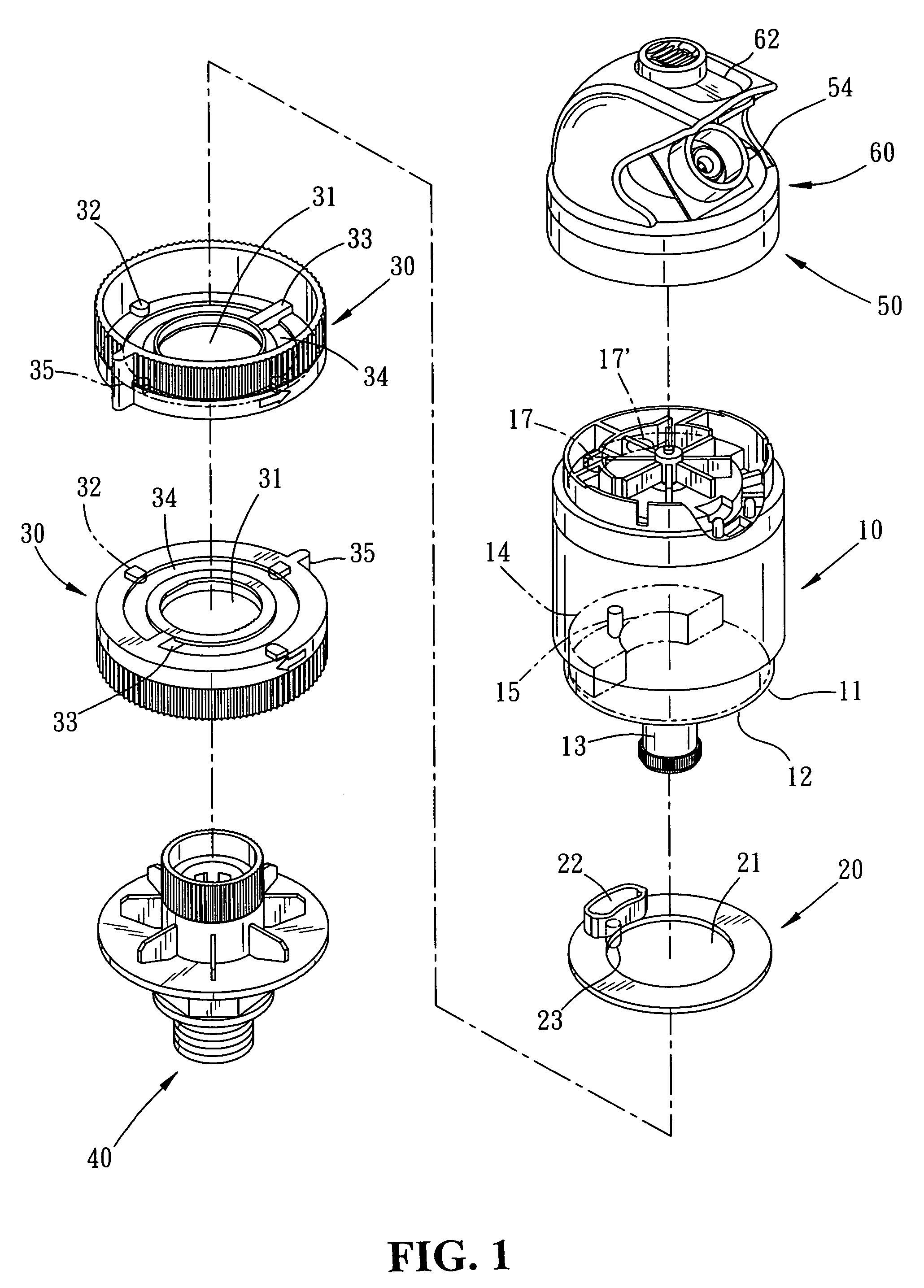
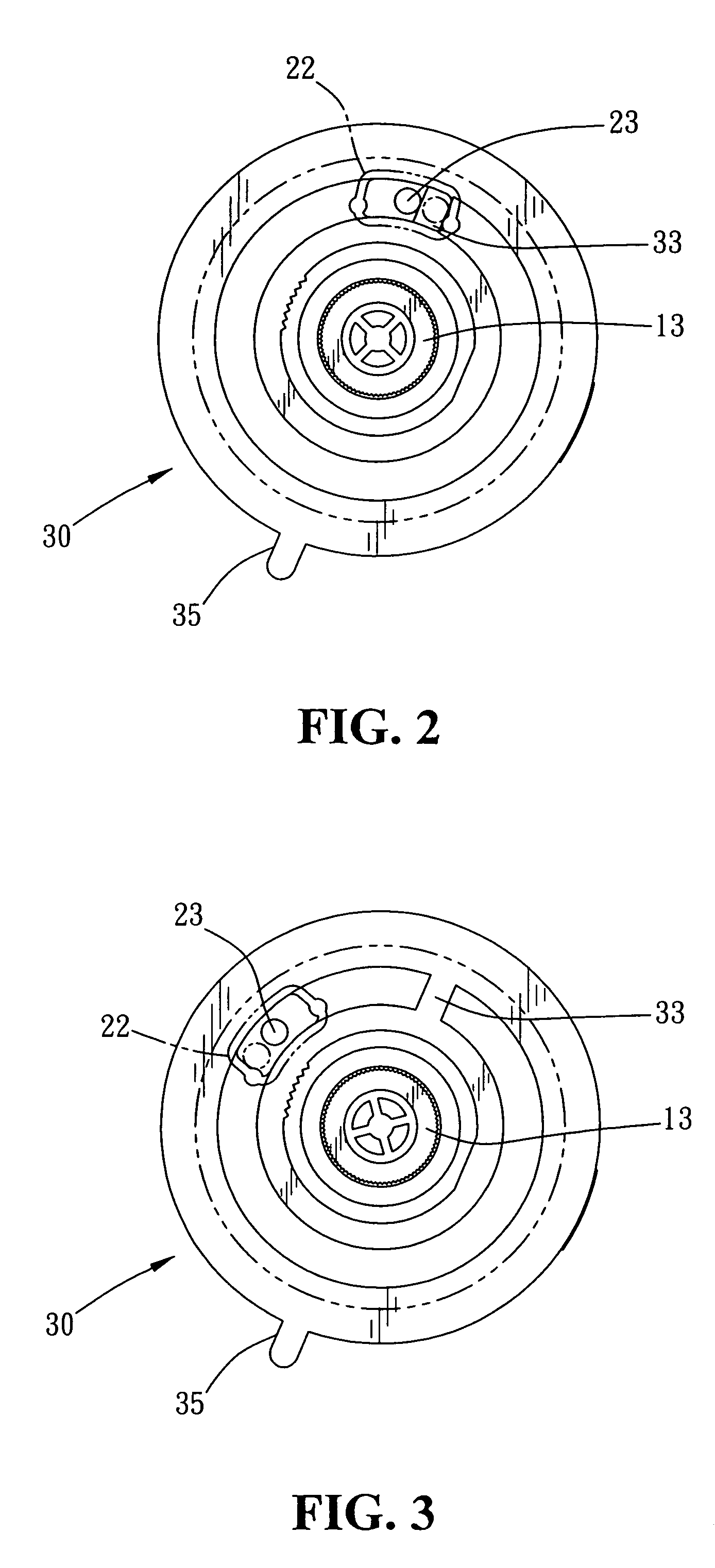
[0024]Please refer to FIGS. 1, 2. The present invention relates to a multifunctional sprinkler structure, comprising a water motor 10, a linking piece 20, two adjusting seats 30, a water supply seat 40, an outlet seat 50, and a top cover 60. The water motor 10 has a bottom-end side 11 with a guide edge 12 extending downwards from the external periphery, and a connector protruding in the middle for the extension of an inlet tube 13 there-through. The bottom-end side 11 has an arcuate guide groove 14 with a restrictive hole indented at one side thereon for the extension of a switch shaft 15 there-through. The linking piece 20 and the two adjusting seats 30 are respectively equipped with a bore 21, 31 extending through the center thereon to be sequentially guided through the inlet tube 13 and mounted to the water motor 10 thereby. The linking piece 20, abutting against the bottom-end side 11, is restricted by the guide edge 12 to keep an even surface therewith. The linking piece 20 has...


PUM


Abstract

A multifunctional sprinkler structure comprises a water motor having an outlet seat and a top cover mounted to a top-end side, and two adjusting seats and a water supply seat assembled onto a bottom-end side. The bottom-end side of the water motor has a guide groove with a restrictive hole for the extension of a switch shaft there-through. The outlet seat has a water-discharge chamber with multiple barriers extending thereon corresponding to an impeller of the water motor, and an oblique-extending central guide port matching to a spray nozzle having multiple water-guiding ribs obliquely extending towards the same direction therein. Therefore, the barriers of the outlet seat and the water-guiding ribs of the spray nozzle are utilized to correspond to the direction of the water flow so that the water discharge can be easily switched to eject either in more direct and forceful column-like spray or in more expanding spray.

Description

BACKGROUND OF THE INVENTION[0001]The present invention relates to a multifunctional sprinkler structure, comprising a water motor having an outlet seat and a top cover mounted to a top-end side, and two adjusting seats and a water supply seat assembled onto a bottom-end side wherein barriers of the outlet seat and water-guiding ribs of the spray nozzle are utilized to correspond to the direction of the water flow so that the water discharge can be easily switched to eject either in more direct and forceful column-like spray or in more expanding spray.[0002]Conventional sprinklers (referring to U.S. Pat. No. 5,611,488 and German Patent No. DE4329616A1) include some disadvantages. For example, when the sprinkling control unit is adjusted to swing to the maximum angle, a switch shaft can hinder the smooth rotation of the sprinkler, which tends to make the sprinkler fail to swing a full 360 degrees and cause uneven distribution of the water discharge sprinkled onto the lawn thereon. Thu...

Claims


Application Information

Patent Timeline
IPC IPC(8): B05B3/16B05B1/12B05B1/26B05B3/04B05B3/08
CPCB05B1/267B05B3/0431Y10S239/01
Inventor LO, SHUN NAN
Owner YUAN MEI CORP
Learn More