Compressor with check valve orientated at angle relative to discharge tube

a technology of compression valve and discharge tube, which is applied in the direction of machines/engines, liquid fuel engines, lighting and heating apparatus, etc., can solve the problems of wear and fatigue breakage of flapper check valves, prone to fatigue and wear failure of check valves, and undesirable reverse rotation for a long time. , to achieve the effect of improving the reliability of check valves and reducing wear

Inactive Publication Date: 2007-08-14
SCROLL TECH
View PDF5 Cites 27 Cited by
  • Summary
  • Abstract
  • Description
  • Claims
  • Application Information

AI Technical Summary

Benefits of technology

[0007]With the inventive positioning of the discharge tube relative to the pivot axis, the flow streamlines heading from the discharge port to the discharge tube are no longer normal to the flapper valve surface, and the amount of wear between the valve moving components and fatigue stresses are reduced. This results in dramatic improvement of the check valve reliability.

Problems solved by technology

Such prolonged reverse rotation is undesirable.
One concern with prior art compressors is the wear and fatigue breakage of these flapper check valves.
This occurs numerous times during any period of operation of the compressor.
Forces acting on these check valves during compressor operation and upon start up and shut down make check valves prone to fatigue and wear failure.
This increases the fluid forces on the flapper check valve, and hence the wear and stresses on the flapper check valve components.

Method used


Image

  • Compressor with check valve orientated at angle relative to discharge tube
  • Compressor with check valve orientated at angle relative to discharge tube
  • Compressor with check valve orientated at angle relative to discharge tube

Examples


Embodiment Construction

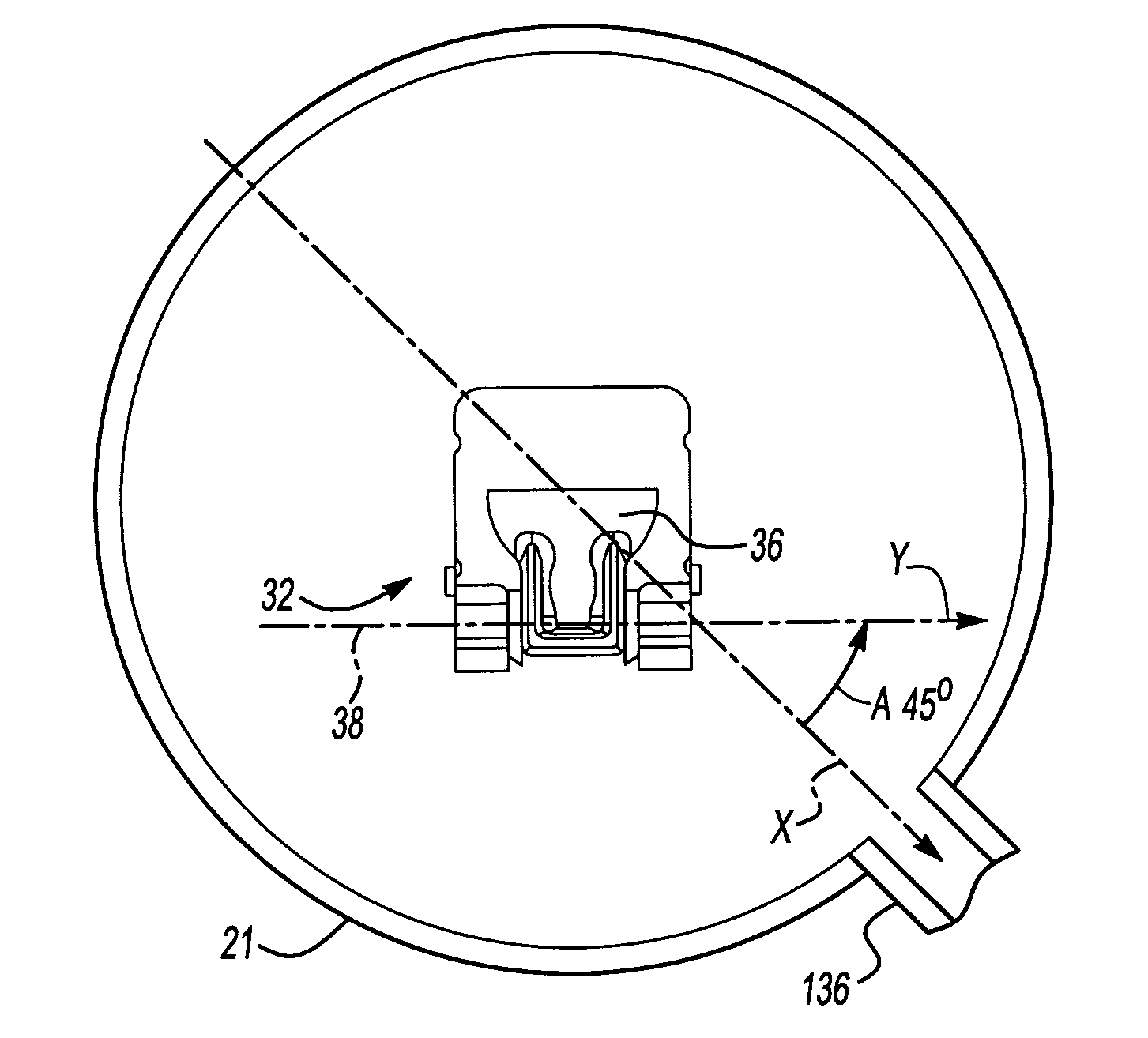
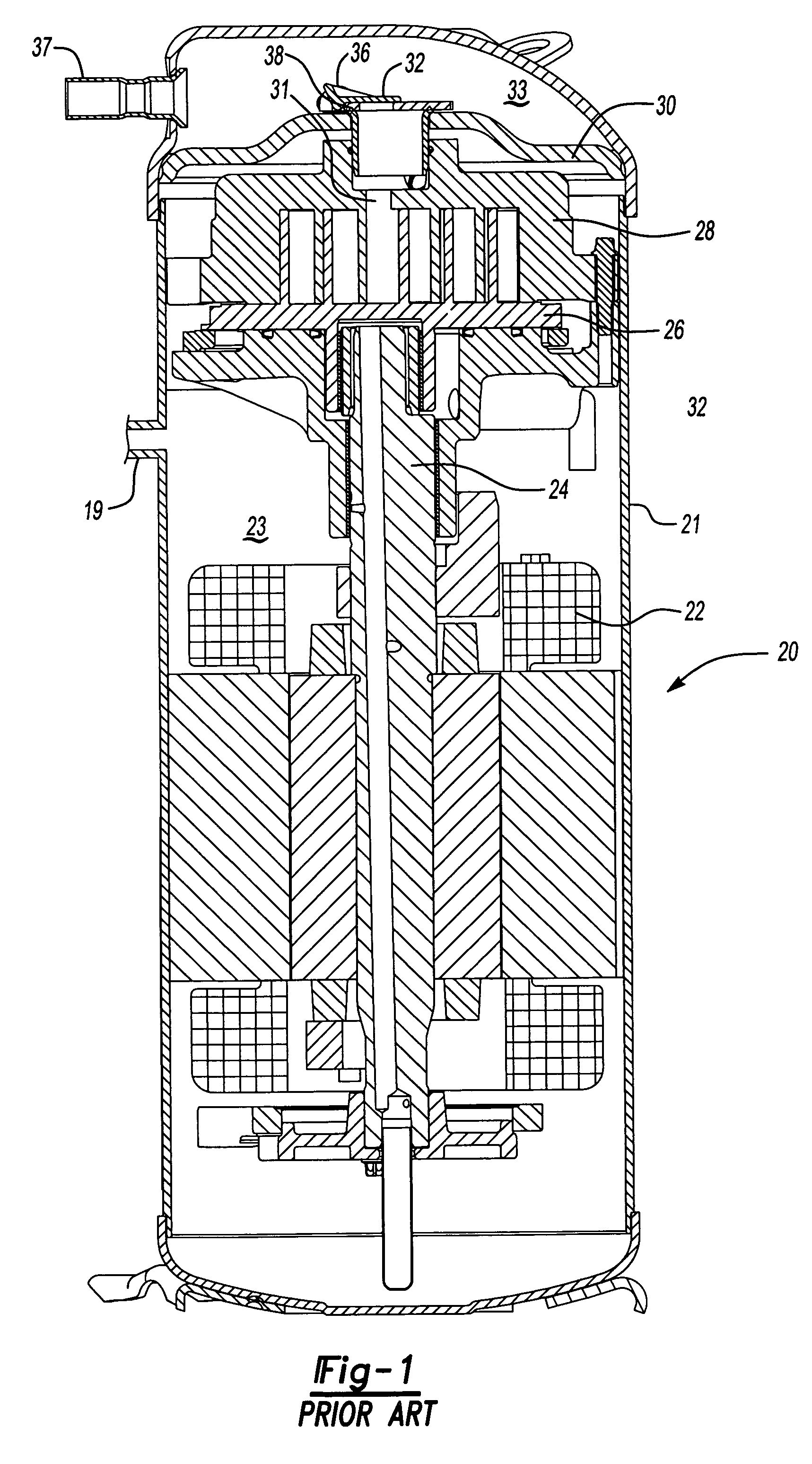
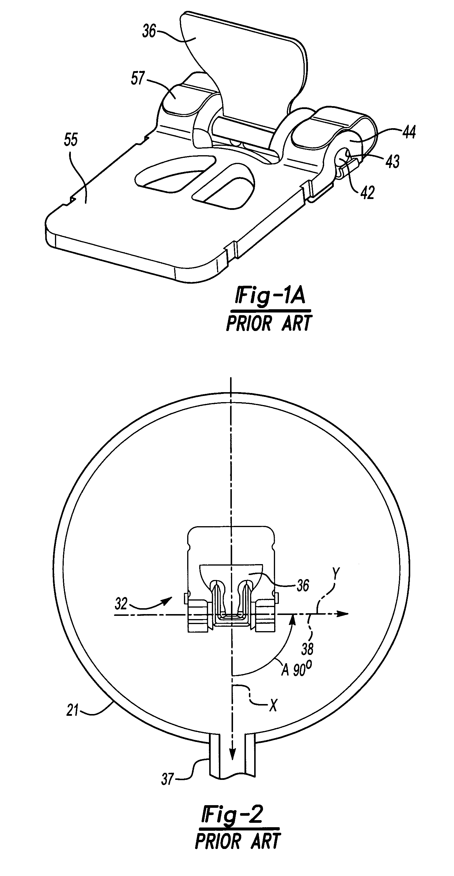
[0014]FIG. 1 shows a prior art compressor 20 incorporating a housing 21 enclosing a motor 22 surrounded by a suction plenum 23. As is known, refrigerant enters the housing 21 through suction port 19 and circulates around the motor 22 and within the suction plenum 23. Refrigerant from the suction plenum 23 moves upwardly into compression chambers defined between an orbiting scroll member 26 and a non-orbiting scroll member 28. As is known, the motor 22 drives a rotating shaft 24 to cause the orbiting scroll 26 to orbit. As further shown, a separator plate 30 divides the inside of the housing 21 into the suction plenum 23 and a discharge plenum 33. A discharge port 31 extends from the compression chambers to pass a compressed refrigerant from the compression chambers into the discharge plenum 33. As shown, a check valve arrangement 32, with the valve shown in closed position, includes a flapper valve member 36. A discharge tube 37 communicates the refrigerant outwardly of the discharg...


PUM


Abstract

A unique positioning of a discharge tube relative to a pivot axis of a check valve in a compressor reduces the wear and fatigue stresses on the pivoting check valve components. The tube is centered on an axis that is non-perpendicular to an axis that is parallel to the pivot axis of the check valve, and in one embodiment was at 45°. With the inventive positioning of the discharge tube relative to the pivot axis, the flow streamlines heading from the discharge port to the discharge tube are no loner normal to the flapper valve surface, and the amount of wear between moving valve components and fatigue stresses are reduced.

Description

BACKGROUND OF THE INVENTION[0001]This application relates to a unique positioning of a discharge tube relative to a pivot axis for a flapper check valve in a compressor.[0002]Compressors are utilized to compress a refrigerant and deliver the compressed refrigerant to a downstream heat exchanger. One type of refrigerant compressor is a scroll compressor. In a scroll compressor, a pair of scroll members each have a base and a generally spiral wrap extending from the base. The wraps interfit to define compression chambers. One of the two scroll members is caused to orbit relative to the other, with the size of the compression chambers decreasing toward discharge as refrigerant is being compressed. After the refrigerant has been compressed, it leaves the compression chambers through a discharge port and into the discharge plenum.[0003]A shell of the compressor is normally divided into a suction plenum and a discharge plenum by a separator plate. Scroll compressors require a check valve ...

Claims


Application Information

Patent Timeline
Patent Type & Authority Patents(United States)
IPC IPC(8): F01C1/063F01C1/00F03C2/00F03C4/00F04C18/00F04C2/00
CPCF04C23/008F04C29/126F25B1/04F04C18/0215
Inventor LIFSON, ALEXANDERFRASER, BRUCE A.
Owner SCROLL TECH
Why Eureka
Try Eureka