Bone milling instrument

a milling instrument and bone technology, applied in bone drill guides, medical science, surgery, etc., can solve the problems of inability to match the internal anatomy of the bone, inability to accurately machine the shape of inability to accurately fit the implant to the bone, etc., to achieve more anatomically correct shape, complex and anatomically correct implant shape, and more complex bone anatomy.

Inactive Publication Date: 2007-08-14
SHALBY ADVANCED TECH INC
View PDF7 Cites 177 Cited by
  • Summary
  • Abstract
  • Description
  • Claims
  • Application Information

AI Technical Summary

Benefits of technology

[0007]Current milling instrumentation systems are unable to machine shapes that match the naturally occurring internal anatomy of the bone. Due to the nature of using revolving cutting tools, the implant designs driven by these instrumentation systems consist of rudimentary combinations of cones and cylinders. Preparing bone for implants of these basic shapes often causes one to compromise the fit of the implant to the bone. The implant cavity prepared with milling is very simple and the anatomy of the bone is much more complex. Implanting non-anatomic geometries requires removing more bone in some areas and less bone in other areas than is desirable. Using the broach / rasp system, more complex and anatomically correct implant shapes can be created in the bone, when compared to those geometries which can be milled into the bone using simple cone and cylinder instrumentation. Although broach / rasp systems can create a more anatomically correct shape in the bone, the act of repeatedly hammering the broach / rasp in and out of the bony canal is imprecise. On the other hand, previous milling systems were able to create accurate holes in the bone which were too simple to be anatomically correct. Anatomically correct implants typically include arcs or compound arcs having parallel or tapered sides. These arcs can be either symmetrically or asymmetrically placed relative to the bulk of the proximal implant geometry.
[0008]The purpose of this invention is to allow the surgeon to create shaped cavities within bones. These cavities have complex and compound arcs of various geometries and are created using rotating cutting tools. The milling instrument can remove a volume of bone while progressing along a path of simple or complex arcs (rotations), single or multiple lines (translations), or a combination of both translations and rotations. These cavities can be created either symmetric or asymmetric relative to any given axis of the bone. This milling instrumentation can be adjusted vertically and horizontally to change the size, shape, and location of the milled cavity to match the anatomic shape of the bone in the region.
[0009]The milling instrument described in this invention is a system of four components: a reference frame, a guidance support member, a reamer shuttle, and a cutting device. The reference frame acts as a support and positional reference for the cutting tool with respect to the bone. The guidance support member controls the path of the cutting tool and thus governs the resulting cavity shape constructed in the bone. The guidance support member can be adjusted in different directions and orientations with respect to the reference frame to alter the shape, size, and location of the cavity created in the bone. The cutting device can be simply a tapered reamer or a revolving cutter of any shape designed to remove material by revolving about its central axis. The reamer shuttle is a component that allows the cutting device to rotate freely while constraining its motion to follow the guidance track. This invention can be a system of components where each of the components is separable and interchangeable with another one of a different size and / or configuration.

Problems solved by technology

Current milling instrumentation systems are unable to machine shapes that match the naturally occurring internal anatomy of the bone.
Preparing bone for implants of these basic shapes often causes one to compromise the fit of the implant to the bone.
Although broach / rasp systems can create a more anatomically correct shape in the bone, the act of repeatedly hammering the broach / rasp in and out of the bony canal is imprecise.
On the other hand, previous milling systems were able to create accurate holes in the bone which were too simple to be anatomically correct.

Method used


Image

  • Bone milling instrument
  • Bone milling instrument
  • Bone milling instrument

Examples


Embodiment Construction

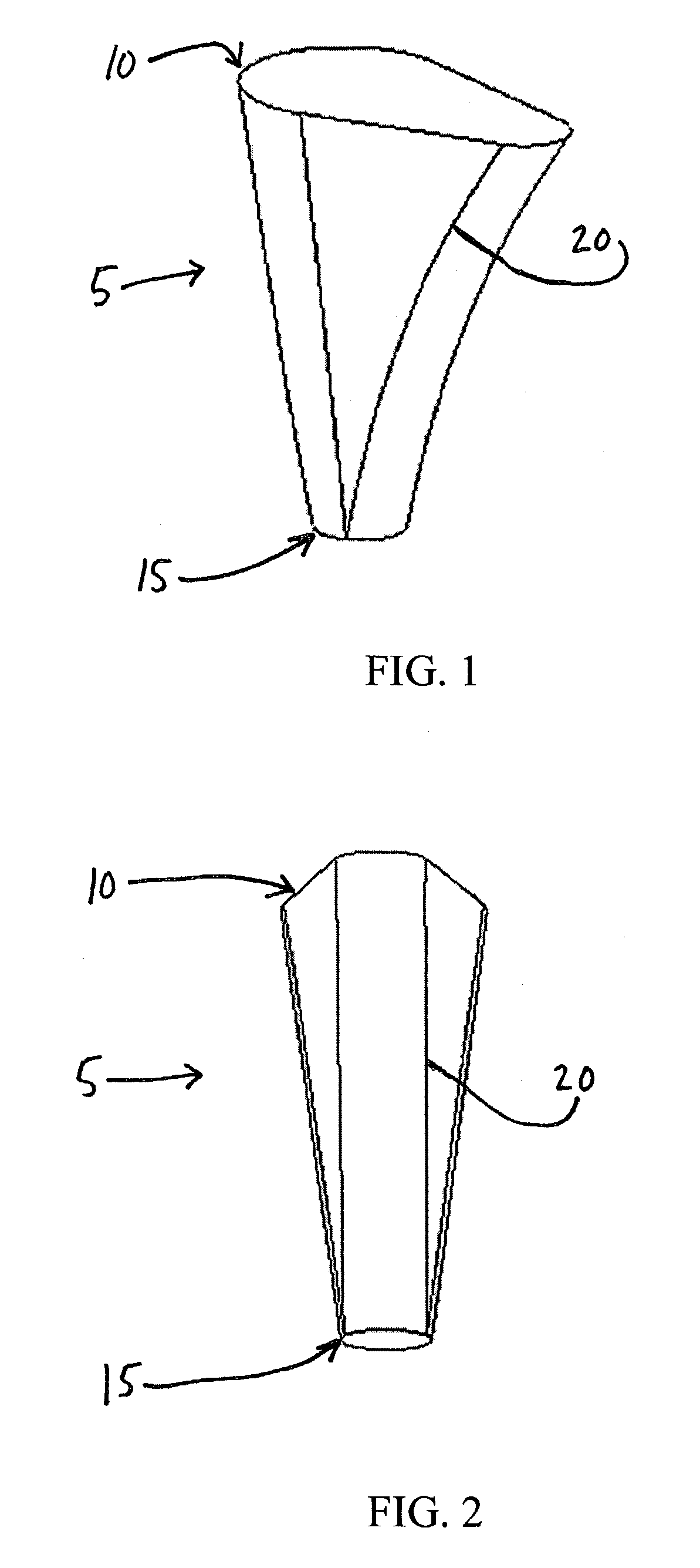
[0021]Referring to FIGS. 1 and 2, and in a preferred embodiment of the present invention, there is shown a first shaped cavity 5, which is illustrated as a solid object 5 but is actually a void within bone (not shown). Such a cavity 5 is preferably wedge shaped and has two ends, including a large end 10 and a smaller end 15, with tapering sides 20 that form at a compound angle to the central axis of the cavity.

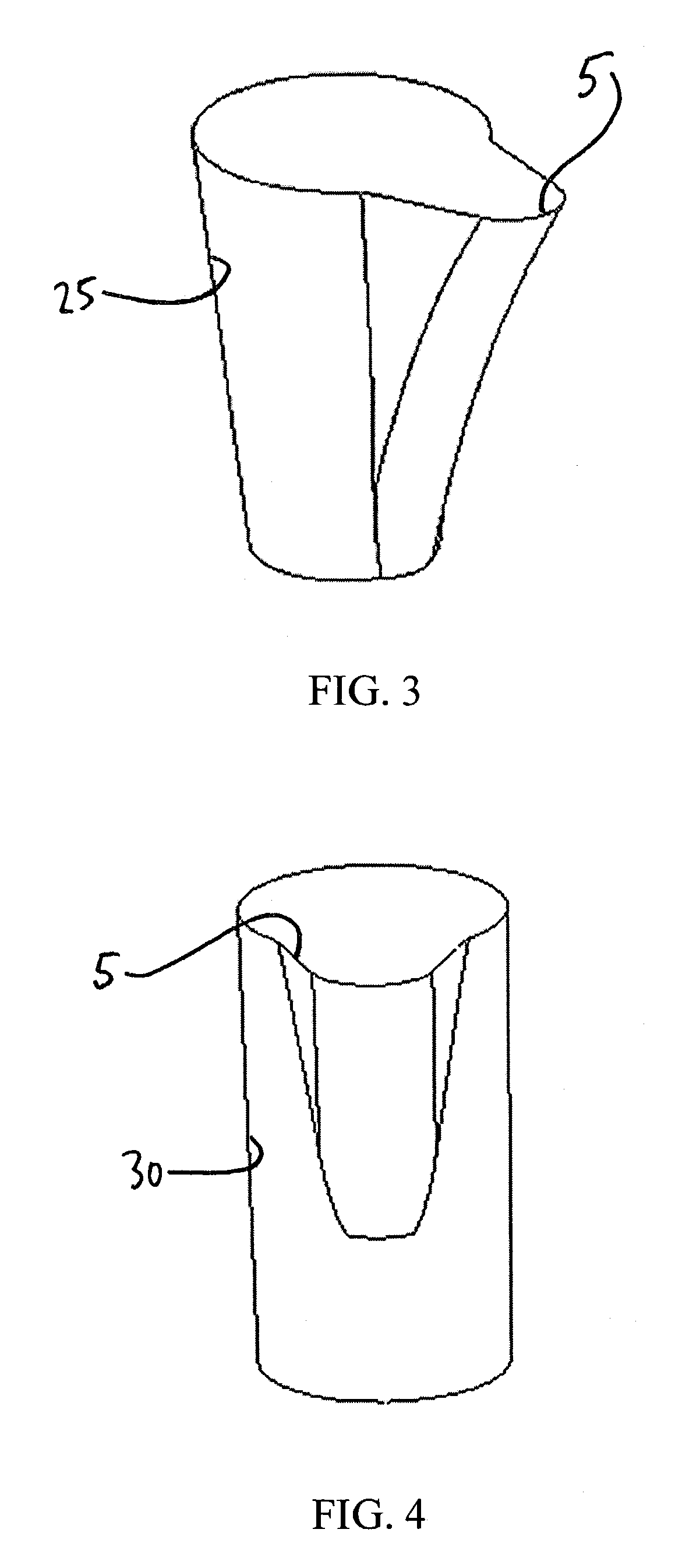
[0022]As shown in FIGS. 3 and 4, tapering cavity 5 can be intersected with other shaped cavities including, but not limited to, a cone 25 (FIG. 3) or a cylinder 30 (FIG. 4), so as to form a composite shape that would conform to the implant.

[0023]Referring now to FIG. 5, there is shown an implant 35 disposed within cavity 5. Cavity 5 has tapering sides designed to transfer loads evenly to the bone as indicated by arrows 40. This configuration will also stimulate bone growth.

[0024]The instrument can create the wedge opening along a curve (such as a medial curve) or along another...


PUM


Abstract

A bone milling instrument is disclosed for creating a shaped cavity from an initial cavity in a bone, the bone milling instrument comprising a reference frame, a centering member at the distal end of the reference frame, a registration surface for engaging a portion of the initial cavity, and an attachment site provided proximally of the registration surface, a guidance support member, an attachment mechanism at the first end of the guidance support member, and a constrained pathway extending between the ends of the guidance support member; a shuttle having a first connection element configured for positionably attaching the shuttle to the guidance support member, and a second connection element configured to provide a rotational coupler; and a cutting device having a cutting portion configured at a distal end thereof, and an attachment portion provided at a proximal end.

Description

REFERENCE TO PENDING PRIOR PATENT APPLICATION[0001]This patent application claims benefit of now abandoned prior U.S. Provisional Patent Application Ser. No. 60 / 378,985, filed May 9, 2002 by Shaun B. Hanson et al. for BONE MILLING INSTRUMENT, which patent application is hereby incorporated herein by reference.FIELD OF THE INVENTION[0002]This invention is related to orthopedic implant apparatus and methods in general, and more particularly to apparatus and methods for creating a shaped cavity in a bone.SUMMARY OF THE INVENTION[0003]This invention provides a bone milling instrument designed to create a cavity in bone for orthopedic implants. The instrument removes a volume of bone using a rotating cutter which progresses along a set path. The shape of the volume of bone is determined by the direction of the set path, the location of the path relative to the bone, and the shape of the cutter and / or cutters used. By engineering the combination of translations and rotations of the cuttin...

Claims


Application Information

Patent Timeline
Patent Type & Authority Patents(United States)
IPC IPC(8): A61B17/00A61BA61B17/16A61B17/17A61B17/58
CPCA61B17/1668A61B17/175
Inventor SERRA, MICHAEL A.HANSON, SHAUN B.DESPRES, III, ALFRED S.
Owner SHALBY ADVANCED TECH INC
Why Eureka
Try Eureka