Asset tracking using wireless LAN infrastructure

a technology of wireless communication link and asset tracking, applied in direction finders using radio waves, instruments, data processing applications, etc., can solve the problems of affecting the performance of other radio frequency applications, and unable to adapt to any other data intensive application

Inactive Publication Date: 2007-08-14
LOCKHEED MARTIN CORP
View PDF25 Cites 25 Cited by
  • Summary
  • Abstract
  • Description
  • Claims
  • Application Information

AI Technical Summary

Problems solved by technology

Unfortunately, current RFID systems are generally custom designed for particular application and / or rely on proprietary, dedicated hardware.
Therefore, such systems can be expanded or modified only with substantial difficulty and cannot be adapted for any other data intensive application.
Further, in general, RFID products from different vendors are not interoperable and, moreover, may interfere with or have their performance degraded by other radio frequency applications, including other RFID systems, used in the same environment.
The geographic scope of the RFID system is generally fixed with the system design and, in general, the detectable range of tags from radio interrogators is very limited, often to a few feet or meters.
Further, the detectable tag of an RFID system may compromise other devices or arrangements that rely on radio frequency communications, particularly compromising reliable communications between terminals and access points of a network.
It should also be recognized that while RFID systems and wireless portions of networks are similar enough in some ways to interfere with each other, the proprietary nature of the former and the intended function of the latter does not permit combined functions to be realized.
For example, while a wireless portion of a network may have a rudimentary capability to track and / or switch the access point for communication with a particular terminal, it cannot generally report the location of the assets that such terminals or particular operators which particular terminals may represent, much less track assets represented by equipment connected to a given terminal which may communicate with a central server or other terminals through a wireless portion of a network.
Conversely, RFID systems cannot provide data communications using standard wireless data networking protocols, such as IEEE 802.11.

Method used


Image

  • Asset tracking using wireless LAN infrastructure
  • Asset tracking using wireless LAN infrastructure
  • Asset tracking using wireless LAN infrastructure

Examples


Embodiment Construction

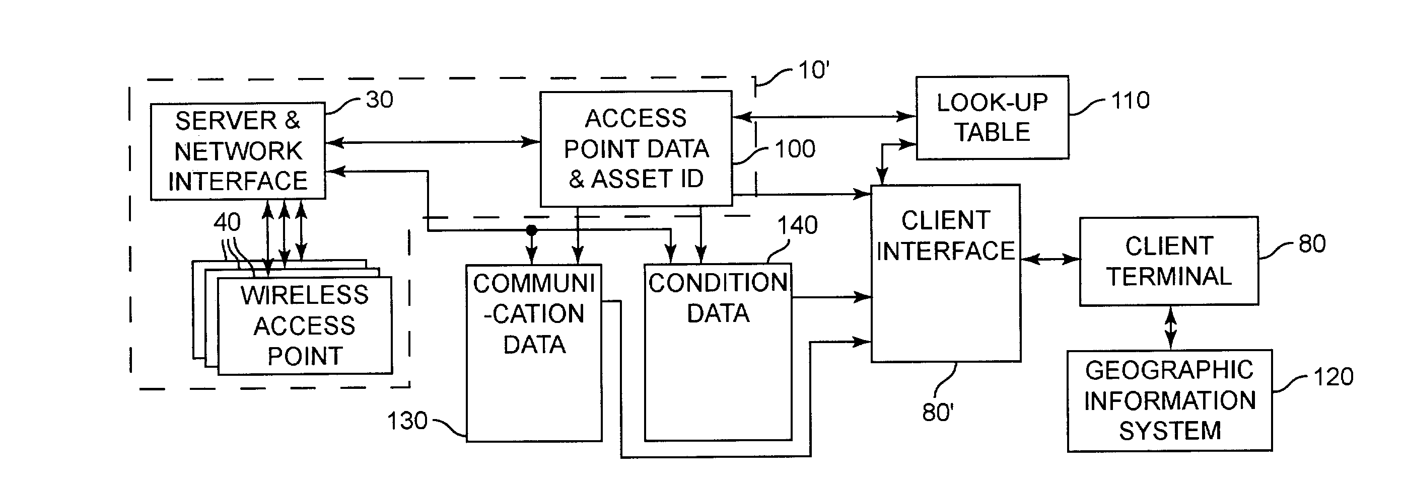
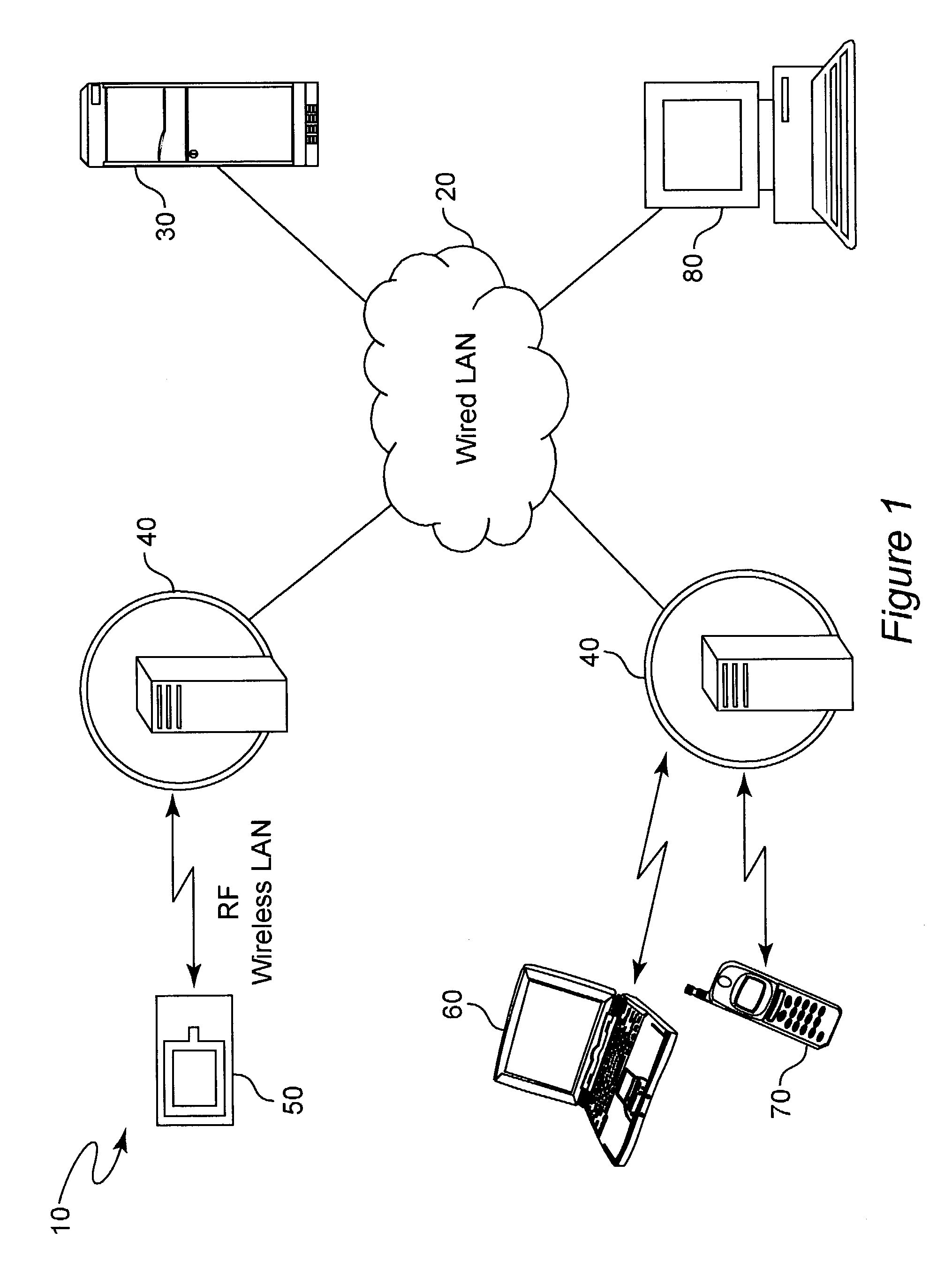
[0019]Referring now to the drawings, and more particularly to FIG. 1, there is shown a high-level schematic diagram of the physical architecture of an exemplary system 10 in accordance with the invention. Central to this system architecture is a wired network of arbitrary extent, the details of which are unimportant to the practice of the invention. Associated with the wired network 20 is a server / controller 30 which is suitably programmed to provide polling or querying of wireless network access points with a simple network management protocol (SNMP), wireless network management protocol (WNMP) or the like as well as database management and client communications applications.

[0020]These queries may serve the simple purpose of determining which devices are associated with which access points, which can then be mapped to physical locations based on proximity. It is preferred that the system feed data from the queries to an algorithm that will provide higher resolution positioning or ...


PUM


Abstract

Transponders capable of providing identification information and possibly additional information are detected from wireless access points of a computer network as a substitute for closed radio frequency identification (RFID) systems while providing numerous additional functionalities and applications. Total asset visibility or responses to more limited queries are provided by inclusion of a geographic information system software application. Location reporting of proximity of devices/transponders to access points can be enhanced to a fine-grained level by triangulation or other algorithms including neural networks.

Description

BACKGROUND OF THE INVENTION[0001]1. Field of the Invention[0002]The present invention generally relates to the tracking of movement of people and objects using wireless communication links and, more particularly, to combined tracking of and communication with people and objects using a widely available and well-developed communications medium.[0003]2. Description of the Prior Art[0004]Radio Frequency Identification (RFID) systems have been known for a number of years, particularly in the field of theft deterrence. Many retail establishments now mark goods with a removable tag or include a permanent device in or on the goods which can be deactivated by a magnetic field or other arrangement. Tags which have not been deactivated or removed are then detected at some point of egress from the store by radio frequency interrogators positioned to detect active tags brought into proximity therewith.[0005]RFID systems are not at all limited to theft deterrence and may be used for a wide varie...

Claims


Application Information

Patent Timeline
Patent Type & Authority Patents(United States)
IPC IPC(8): H04Q5/22G01S3/02
CPCG06Q10/08
Inventor MOODY, JOHN O.STEINBRECHER, ERIC R.
Owner LOCKHEED MARTIN CORP
Why Eureka
Try Eureka