
Control apparatus for internal combustion engine

a technology of control apparatus and internal combustion engine, which is applied in the direction of electric control, machines/engines, instruments, etc., can solve the problem of properly identifying the fuel system

Active Publication Date: 2007-08-21
TOYOTA JIDOSHA KK
View PDF18 Cites 17 Cited by
  • Summary
  • Abstract
  • Description
  • Claims
  • Application Information

AI Technical Summary

Benefits of technology

The present invention provides a control apparatus for identifying errors in the fuel system of an internal combustion engine that includes at least two fuel systems and fuel injection mechanisms connected to each system. The control apparatus senses the pressure of fuel at the first fuel system and determines if there is an increase in pressure caused by heat from the engine. This allows for the proper identification of errors in the fuel system, such as leaks, and ensures the engine operates efficiently with the fuel injection mechanisms. The first fuel system injects fuel directly into the cylinder at high pressure, and the second fuel system injects fuel into the intake manifold or port. The control apparatus can identify errors in the first fuel system using an in-cylinder injector and an intake manifold injector.

Problems solved by technology

As a result, an error in the fuel system can be identified properly in an internal combustion engine that includes at least a first fuel injection mechanism having fuel supplied from the first fuel system to inject fuel into a cylinder, and a second fuel injection mechanism having fuel supplied by the second fuel system to inject fuel into the intake manifold.

Method used


Image

  • Control apparatus for internal combustion engine
  • Control apparatus for internal combustion engine
  • Control apparatus for internal combustion engine

Examples


Embodiment Construction

[0026]Embodiments of the present invention will be described hereinafter with reference to the drawings. The same elements have the same reference characters allotted. Their designation and function are also identical. Therefore, detailed description thereof will not be repeated.

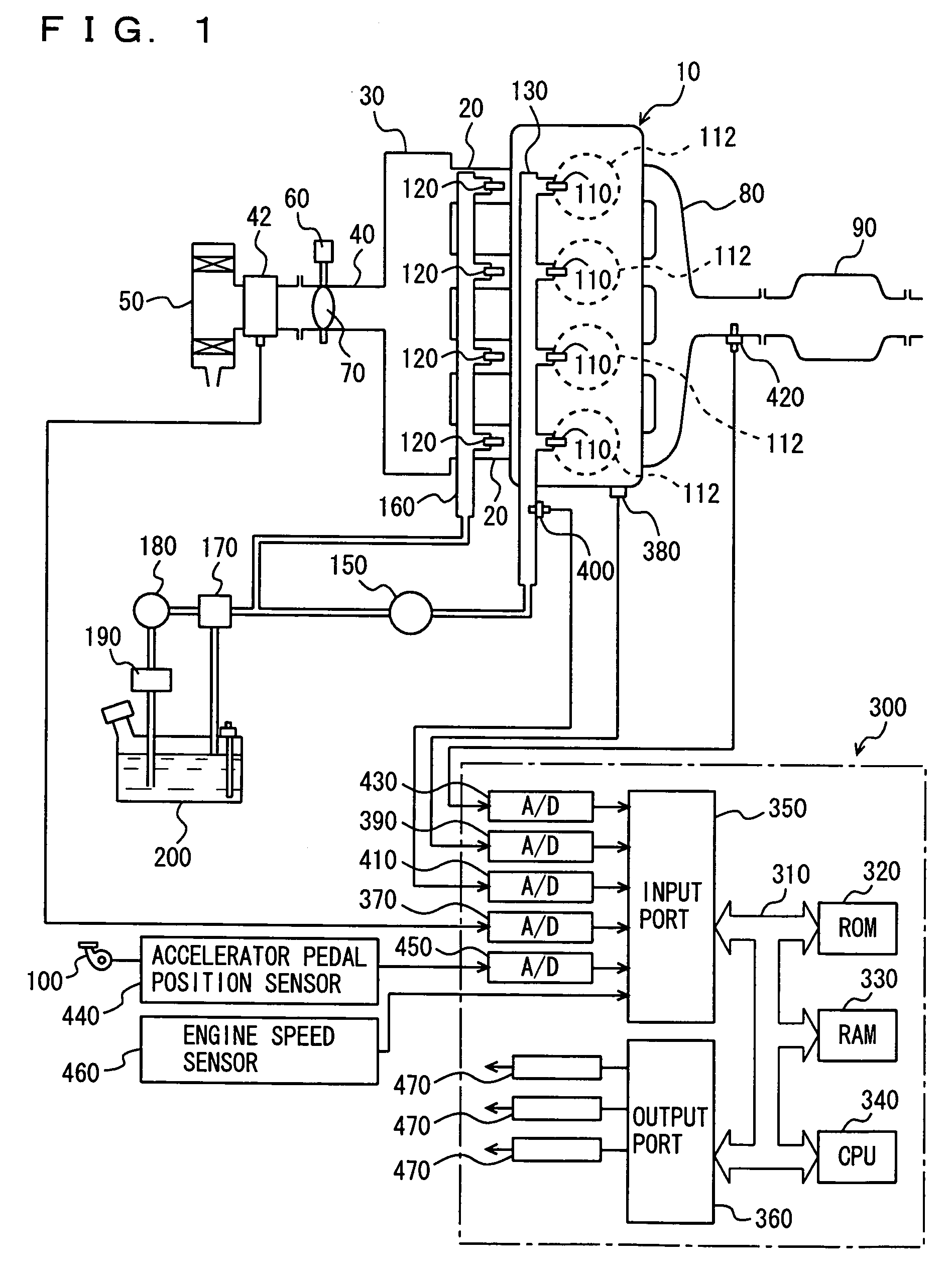
[0027]FIG. 1 schematically shows a configuration of an engine system under control of an engine ECU (Electronic Control Unit) qualified as a control apparatus for an internal combustion engine according to a first embodiment of the present invention. Although an in-line 4-cylinder gasoline engine is shown in FIG. 1, application of the present invention is not limited to the engine shown, and a V-type 6-cylinder engine, a V-type 8-cylinder engine, an in-line 6-cylinder engine, and the like may be employed. The present invention is applicable as long as the engine includes at least an in-cylinder injector and an intake manifold injector for each cylinder.

[0028]Referring to FIG. 1, an engine 10 includes four cy...


PUM


Abstract

An engine ECU executes a program including the steps of: when the port fuel injection ratio is 100% (YES at S200), sensing the engine coolant temperature THW (S210); when the engine coolant temperature THW is higher than a threshold value (YES at S220), monitoring fuel pressure P in a high-pressure delivery pipe (S230); and when fuel pressure P rises by the received heat (YES at S240), identifying that there is no error at the high-pressure fuel system.

Description

[0001]This nonprovisional application is based on Japanese Patent Application No. 2005-213663 filed with the Japan Patent Office on Jul. 25, 2005, the entire contents of which are hereby incorporated by reference.BACKGROUND OF THE INVENTION[0002]1. Field of the Invention[0003]The present invention relates to a control apparatus to identify an error occurring at a fuel system of an internal combustion engine that includes a fuel injection mechanism (in-cylinder injector) injecting fuel at high pressure into a cylinder and a fuel injection mechanism (intake manifold injector) injecting fuel towards an intake manifold or intake port. Particularly, the present invention relates to a control apparatus properly identifying an error at a high-pressure fuel system.[0004]2. Description of the Background Art[0005]There is known an engine including a first fuel injection valve (in-cylinder injector) for injecting fuel into the combustion chamber of a gasoline engine and a second fuel injection...

Claims


Application Information

Patent Timeline
Patent Type & Authority Patents(United States)
IPC IPC(8): F02M51/00
CPCF02D41/221F02D41/3094F02D41/3809F02M63/029F02D2041/224F02D2041/225F02D2200/0602
Inventor TAHARA, TATSUYAKINOSE, KENICHI
Owner TOYOTA JIDOSHA KK
Learn More