Vertical mount disc brake with disc separator

a technology of disc separator and vertical mount, which is applied in the direction of brake types, actuators, braking elements, etc., can solve the problems of premature brake failure and poor performance of failsafe brakes, and achieve the effect of reducing heat buildup

Active Publication Date: 2007-08-21
LAMBERT BRAKE
View PDF13 Cites 19 Cited by
  • Summary
  • Abstract
  • Description
  • Claims
  • Application Information

AI Technical Summary

Benefits of technology

[0006]It is a further object of the present invention to provide a brake, as above, which reduces heat buildup while disengaged.
[0007]It is an additional object of the present invention to provide a brake, as above, which is efficient.
[0009]In general, a brake is provided which includes a housing. A shaft is positioned within the housing and is rotatable about an axis. A disc assembly includes a plurality of stationary discs coupled to the housing and a plurality of rotating discs carried by the shaft. The rotatable discs are positioned to be engaged by the stationary discs. A spacing assembly is positioned on the shaft such that when the disc assembly is disengaged, the spacing assembly axially separates the rotating discs. This reduces frictional contact with the stationary discs.
[0011]In accordance with yet another aspect of the present invention, a brake for applying a braking force to an external shaft includes a housing. An inner shaft is adapted to be coupled with the external shaft and rotatable about an axis. A disc assembly includes a plurality of stationary discs carried by the housing and a plurality of rotating discs carried by the shaft. The rotatable discs are adapted to selectively engage the stationary discs. The disc assembly is positioned in a vertically upstanding orientation defining a bottom end and a top end. A washer is coupled to the shaft and positioned proximate to the bottom end of the disc assembly. A plurality of o-rings are interposed between each of the rotating discs and between the washer and a rotating disc. The washer and the o-rings vertically separate the rotating discs thereby minimizing frictional contact between the rotating discs and the stationary discs when the rotatable discs are not engaging the stationary discs.

Problems solved by technology

In these applications, prior art, failsafe brakes perform poorly.
While the forces of gravity do not create enough clamping force to stop shaft movement altogether, the gravitational clamping of the disc assembly causes unwanted heat and friction and leads to premature brake failure.

Method used


Image

  • Vertical mount disc brake with disc separator
  • Vertical mount disc brake with disc separator
  • Vertical mount disc brake with disc separator

Examples


Embodiment Construction

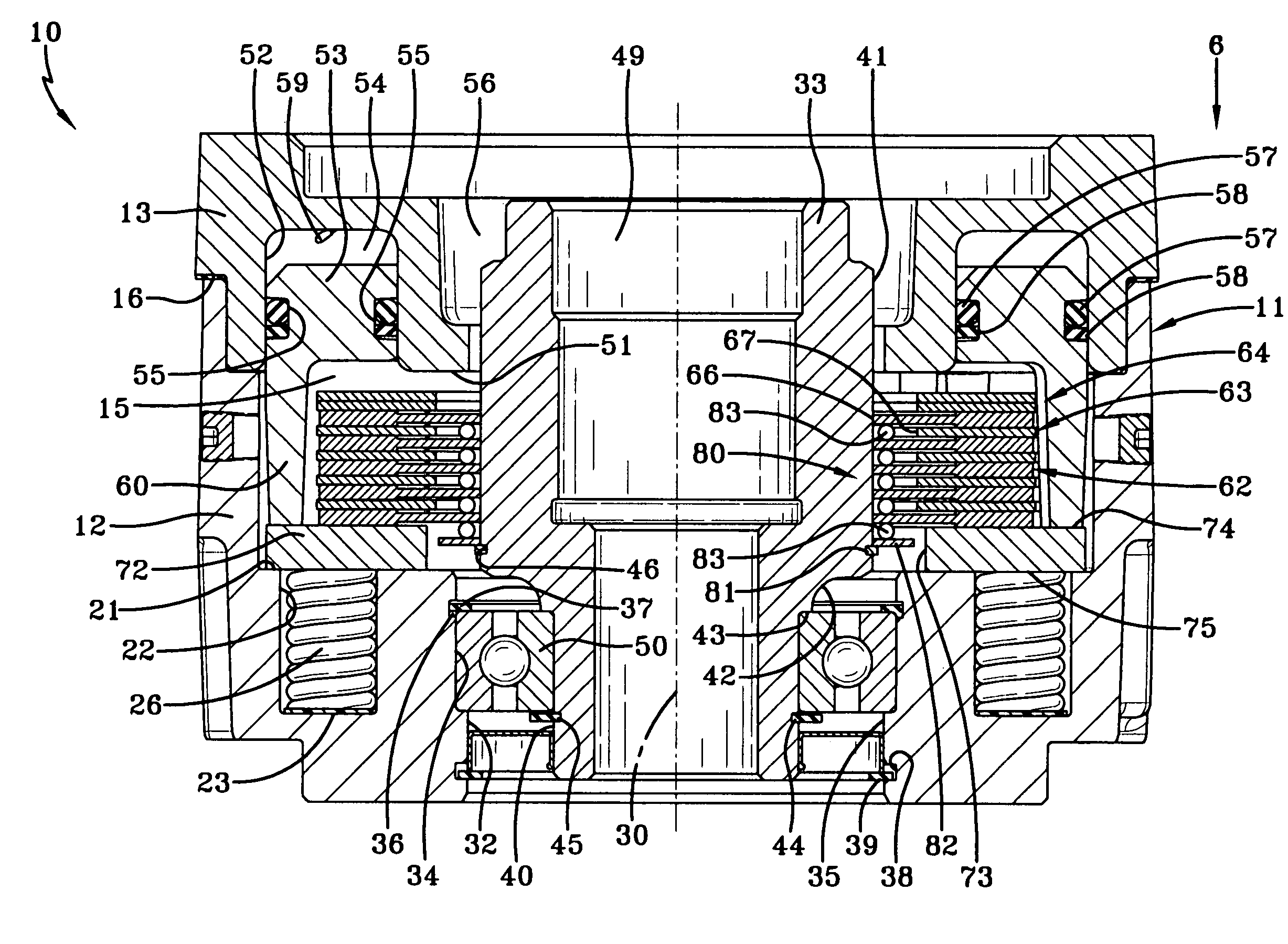
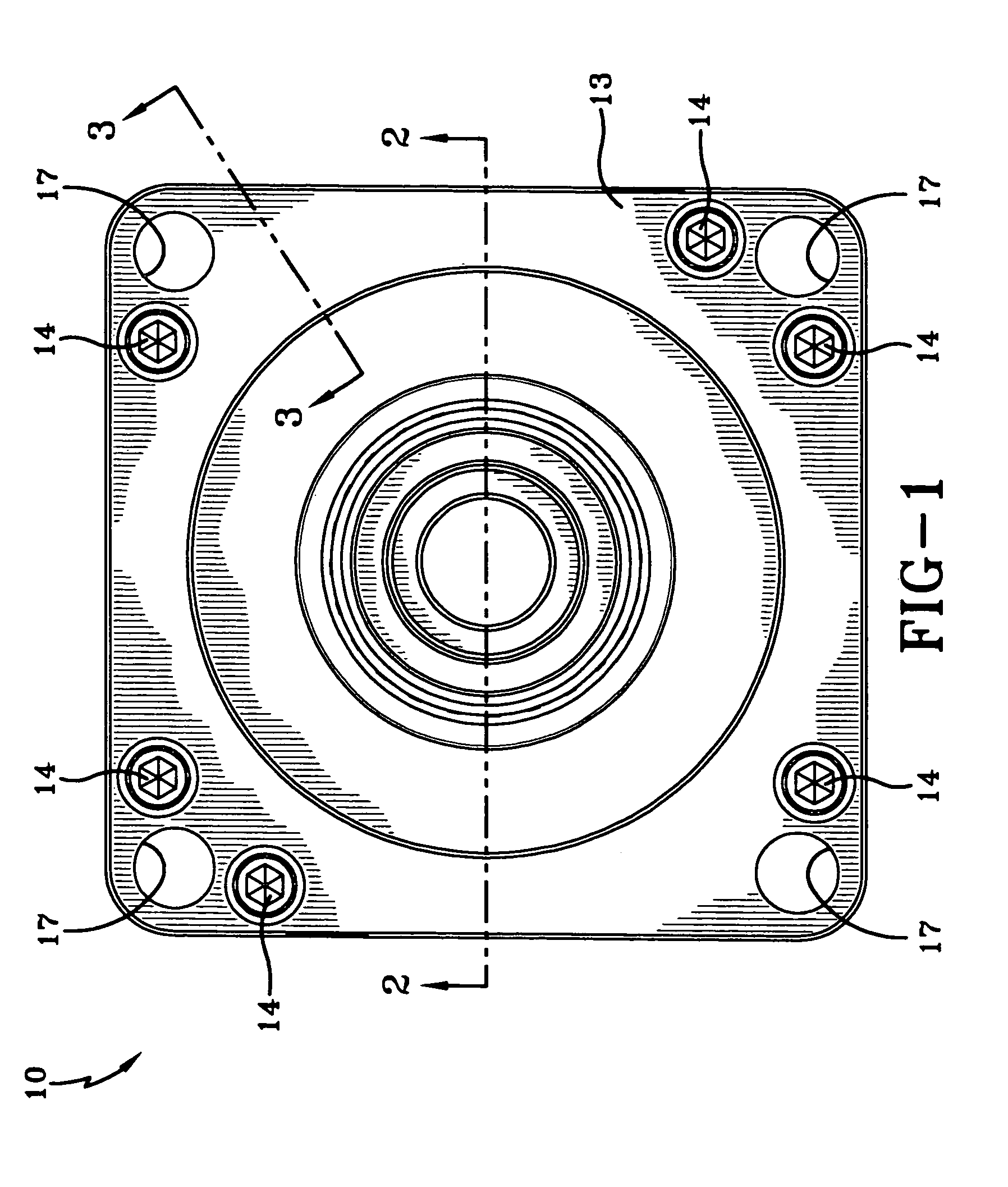
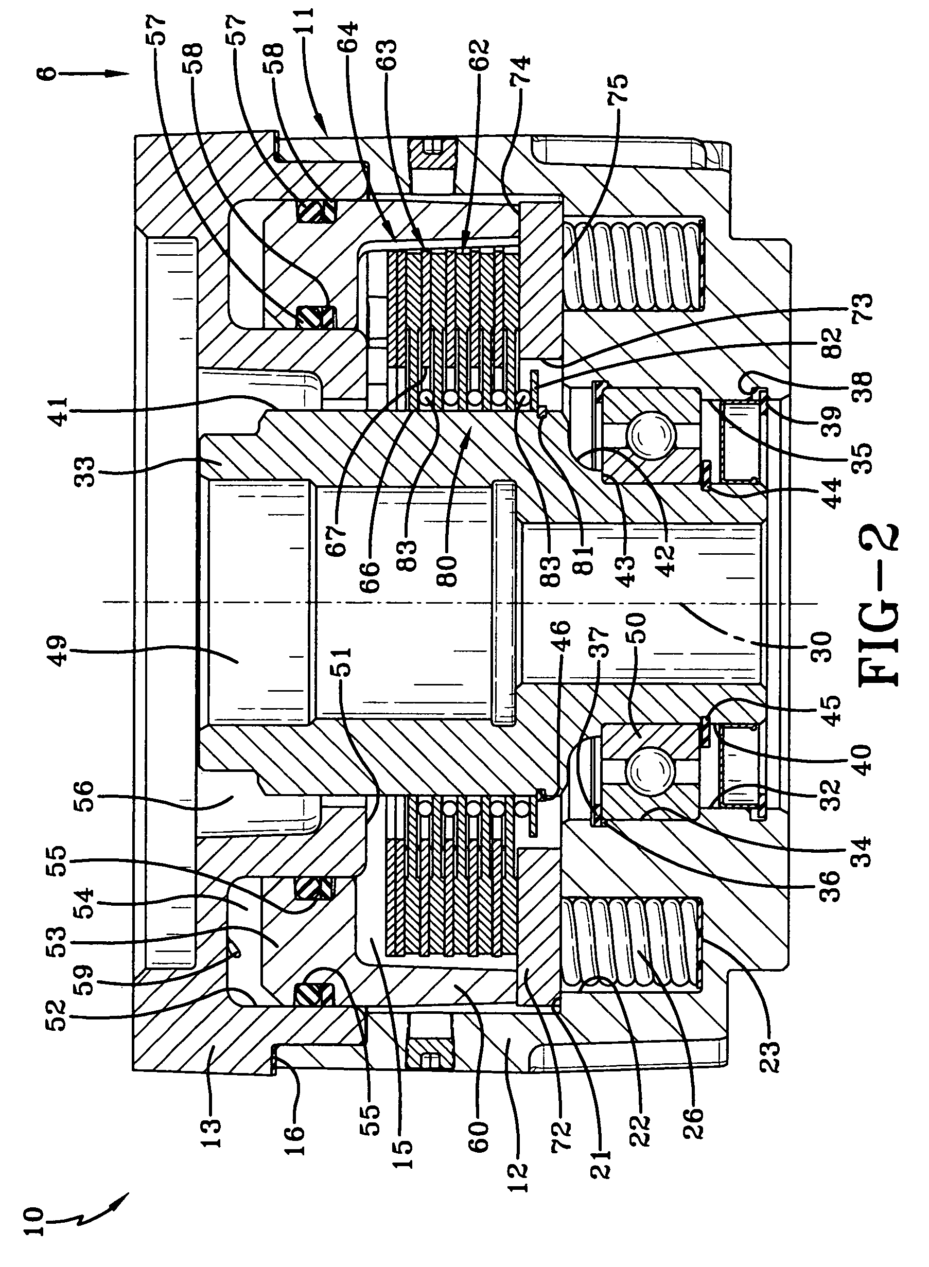
[0017]A brake made in accordance with the present invention is indicated generally by the numeral 10 and includes a housing assembly 11 which contains and protects the working brake components in addition to providing means to mount the brake 10 to a piece of equipment. Housing assembly 11 includes a main housing 12 and a power plate 13. Main housing 12 is generally cylindrical in configuration having an open end. Power plate 13 is coupled to main housing 12 at the open end by a plurality of bolts 14. Thus configured, main housing 12 and power plate 13 define a cavity 15 which retains the working brake components as will be hereinafter discussed. A gasket 16 may be provided between a portion of the mating surface of main housing 12 and power plate 13, thereby preventing contamination of the lubricants within cavity 15. Main housing 12 and power plate 13 further include a plurality of bores 17 which are aligned and extend through housing assembly 11. Bores 17 provide a means to attac...


PUM


Abstract

A brake (10) which is adapted to be rotationally coupled with an output shaft includes a housing (11). An inner shaft (33) is adapted to be attached to the output shaft for rotation therewith. A disc assembly (64) includes a plurality of stationary discs (63) carried by the housing (11) and a plurality of rotating discs (62) carried by the inner shaft (33). The rotatable discs (62) are positioned to be engaged by the stationary discs (63). A least one spring (26) biases the stationary discs (63) to engage the rotatable discs (62). A piston (53) is movable to oppose the force of the spring (26). A spacing assembly (80) is positioned on the inner shaft (33) and rotatable therewith. The spacing assembly (80) includes a plurality of o-rings (83) to separate the rotating discs (62) a predetermined axial distance from an adjacent rotating disc (62).

Description

TECHNICAL FIELD[0001]This invention relates to a failsafe brake operable in a substantially vertical orientation. More specifically, this invention relates to such a brake wherein the discs are separated by a plurality of spacers, thus reducing friction when the brake is unactuated.BACKGROUND ART[0002]Many forms of heavy equipment require failsafe brake systems in order to ensure safe operation. In general, failsafe brake systems include a plurality of springs which urge a disc assembly to clamp together, thereby applying a braking torque to a shaft. A piston opposes the spring force, and when pressure is supplied to the piston, the brake is released for normal operation. In this manner, if during operation, power is lost to the equipment, the springs clamp the disc assembly together preventing rotation of the shaft until power is restored.[0003]In one particular application, the shaft which requires a failsafe brake is positioned in a substantially vertical orientation, such as is ...

Claims


Application Information

Patent Timeline
Patent Type & Authority Patents(United States)
IPC IPC(8): F16D65/24F16D65/22
CPCF16D55/36F16D2065/1396F16D2121/12
Inventor DENNIS, BRIAN P.POZIVILKO, PETER J.SCHNELL, RAY F.
Owner LAMBERT BRAKE
Why Eureka
Try Eureka