
Diving apparatus

a technology of diving apparatus and scuba diving, which is applied in the direction of life-saving, waterborne vessels, life-buoys, etc., to achieve the effect of substantial safety

Inactive Publication Date: 2007-08-21
ELLWITZ MARTIN
View PDF4 Cites 2 Cited by
  • Summary
  • Abstract
  • Description
  • Claims
  • Application Information

AI Technical Summary

Benefits of technology

[0007]The disadvantages of the prior art resulted in developing the diving apparatus of the type mentioned at the beginning to the effect that diving with such an apparatus gains substantially in safety and the user is capable of reacting appropriately to unforeseen circumstances.
[0008]In order to achieve the object, the invention proposes, starting from the diving apparatus of the type mentioned at the beginning, that the diving weights are detachably fastened, for example via surface zip fasteners, on the fresh air tank, and can therefore be removed easily. Furthermore, it is the subject matter of the invention that the pulling means between the pump and the limb on which it is fastened has a quick release device which permits easy separation of the pulling means. Furthermore, it is proposed that the float is surrounded by a net which permits the diver to hold on to the float. In addition to the abovementioned developments, it is likewise the subject matter of the invention that the float has a seat arranged below the water surface. It is proposed, furthermore, that the belts by means of which the fresh air tank is fastened on the diver in each case have at least one quick fastener which can easily be opened by the diver.
[0009]A particular advantage of the inventive fastening of the diving weights by means of surface zip fasteners on the fresh air tank resides in the ease with which these diving weights can be removed. Should the diver get into a dangerous situation necessitating rapid ascent, he can remove the diving weights by a simple reflex action of ripping them off the fresh air tank and, thereby rendered lighter, can safely reach the maturing surface, possibly with the aid of the buoyancy of the residual air still present in the fresh air tank. The surface zip fastener is particularly well suited to such a connection, since it ensures a virtually uninterruptedly firm connection independently of the ambient medium. The diving weights are reliably held both during transport of the diving apparatus on land and when it is being used in the water. Despite the enormous load-bearing capacity of the connection with a surface zip fastener, introducing force at the edge of the surface zip fastener connection suffices to cancel the adhesion. The originally two-dimensionally distributed load is concentrated during the release operation onto a narrow line, and this ensures that any person is capable of dumping the diving weights irrespective of individual bodily strength.

Problems solved by technology

The disadvantages of the prior art resulted in developing the diving apparatus of the type mentioned at the beginning to the effect that diving with such an apparatus gains substantially in safety and the user is capable of reacting appropriately to unforeseen circumstances.

Method used


Image

  • Diving apparatus
  • Diving apparatus
  • Diving apparatus

Examples


Embodiment Construction

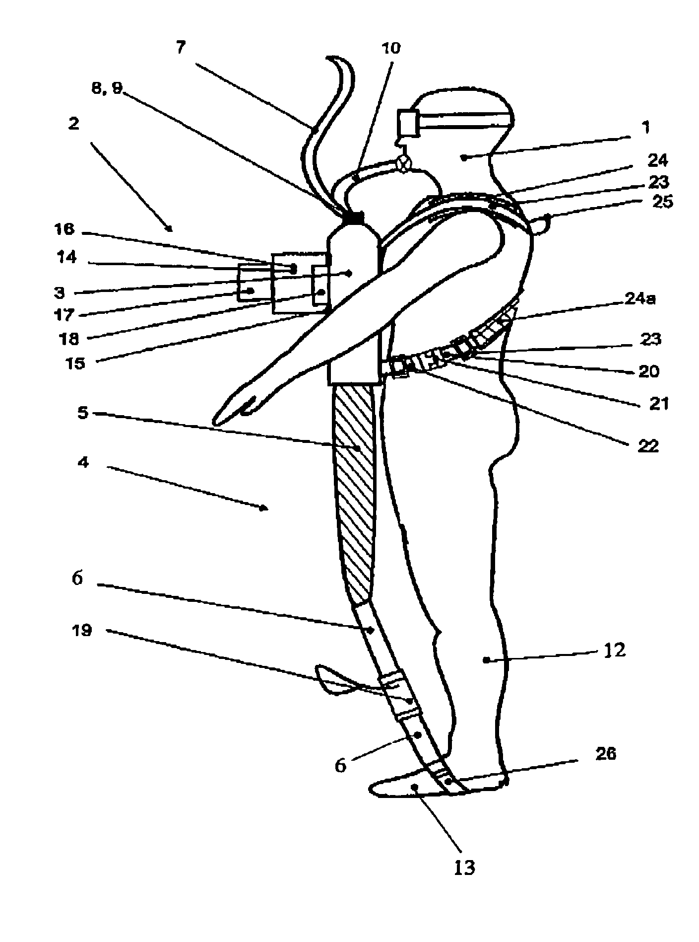
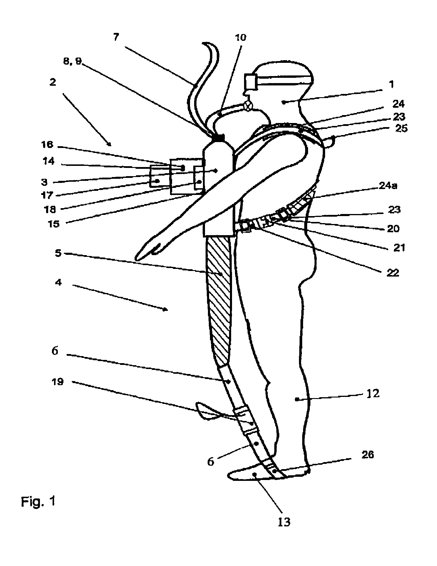
[0054]As a rule, the diver 1 wears the diving apparatus 2 according to the invention on his breast. The diving apparatus 2 comprises a fresh air tank 3 with a pump 4 in the form of an elastic hollow body 5 which is pulled out by the diver 1 via a pulling means 6 in order always to pump the fresh air from the fresh air tank 3.

[0055]The fresh air is supplied via a fresh air line 7 which is connected to the fresh air tank 3 via a first valve 8. The first valve 8 prevents backflow of the fresh air to the air atmosphere. Via a second valve 9, the diver 1 is able to breath in the fresh air located in the fresh air tank 3 through the breathing air line 10 and the mouthpiece 11.

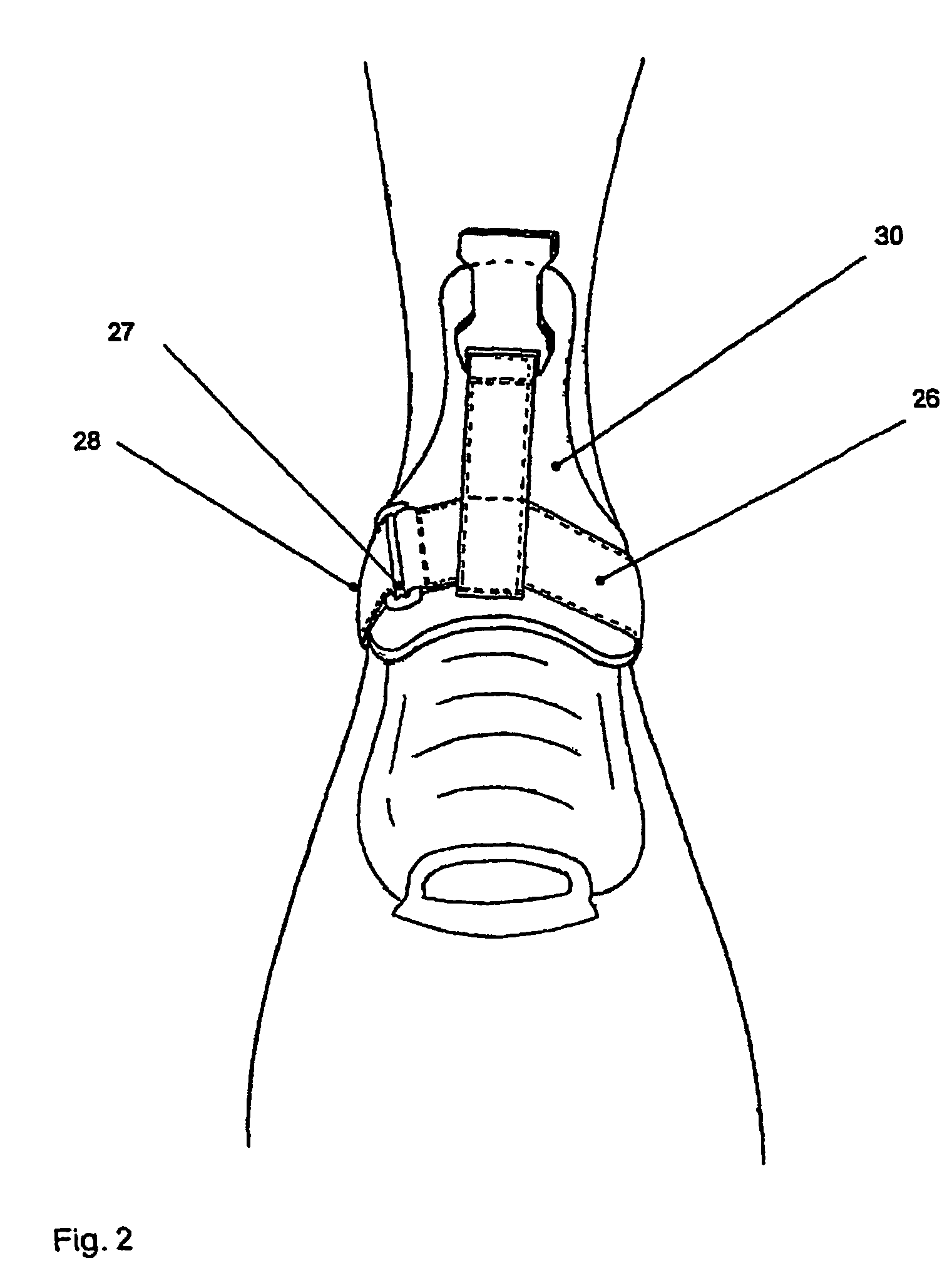
[0056]The pump 4 is actuated by the legs 12, the pulling means 6 being fitted on the foot 13 by means of a fastening. Diving weights 14 are fitted on the fresh air tank 3 via surface zip fasteners 15. These diving weights are containers 16 which are preferably to be filled with sand. Located next to the diving weight...


PUM


Abstract

A diving apparatus includes a pump that is actuated by muscular force. Diving weights are fastened to a fresh-air tank by surface zip fasteners. A traction element lies between the pump and the diver's limbs and to which it is attached a quick-release device. A float is surrounded by a net, the float having a seat located below the surface of the water and each of the straps, which are used to fasten the fresh-air tank to the diver, has at least one quick fastener which can be opened by the diver.

Description

BACKGROUND OF THE INVENTION[0001]The invention relates to a diving apparatus for supplying a diver with breathing air, having a float on which a fresh air line leading from the air atmosphere to the diver is fitted, having a pump which is to be actuated by muscular force and by means of which the diver conveys fresh air via the fresh air line into a fresh air tank which can be worn and fastened on the body of the diver, having a first valve in the fresh air line between the fresh air tank and the air atmosphere, which prevents backflow of the fresh air into the air atmosphere, having a breathing air line which is connected with one end to the fresh air tank, having a mouthpiece which is arranged at the other end of the breathing air line, having a second valve, which is arranged on the breathing air line between the fresh air tank and the mouthpiece, having at least one pulling means, which is actuated at least with a leg or arm and permits the actuation of the pump by the leg or ar...

Claims


Application Information

Patent Timeline
IPC IPC(8): B63C11/20B63C11/30
CPCB63C11/20B63C11/30B63C11/207B63C11/205
Inventor ELLWITZ, MARTIN
Owner ELLWITZ MARTIN
Learn More