Guide blade fixture in a flow channel of an aircraft gas turbine

a technology of flow channel and guide blade, which is applied in the direction of machines/engines, stators, liquid fuel engines, etc., can solve the problems of inherently stable guide blade segments, no integral, and increasing the axial extension of transition channels with greater differences between the radii of channel cross-sections, so as to achieve simple and safe operation, significant weight and cost advantages, and simple and accurate production of these parts.

Inactive Publication Date: 2007-08-21
MTU AERO ENGINES GMBH
View PDF9 Cites 30 Cited by
  • Summary
  • Abstract
  • Description
  • Claims
  • Application Information

AI Technical Summary

Benefits of technology

[0009]The design pursuant to the invention has a series of advantages. For example, a simple and safely functioning seal of the guide blade segments on the inside and outside, and thus to the disk area between the high-pressure and low-pressure turbine, is possible through the straight surface contact between the bars and bearing surfaces of the housing and the bearing pedestal. Through the groove-hook-type connection in the front area of the outer platform of the guide blade segment, these are held radially in the turbine housing in a safe and permanent fashion and are fixed in the circumferential direction by means of the pins engaging in the groove-hook-type connection. The bearing area located on the turbine housing for accommodating the guide blade segment can at the same time serve as a bearing area for a channel segment of the transition channel engaging likewise on the bearing surface so that the mounted guide blade segment of the transition channel is a locking element for the channel segment arranged upstream.
[0010]The arrangement pursuant to the invention of the grooves on the groove-hook-type connection on the housing and the arrangement of the hooks on the outside platform part of the channel segment enables a simple and accurate production of these parts, leading to significant weight and cost advantages.

Problems solved by technology

Such engines furthermore have high bypass ratios and low speeds of the low-pressure turbine shaft, which is generally separated in relation to the high-pressure turbine shaft; moreover the urgency exists to design the core engines in an increasingly compact and powerful manner, which leads to increasingly longer axially extending transition channels with greater differences between the radii of the channel cross-sections that need to be taken into consideration.
Hence, no integral, inherently stable guide blade segments exist.
In the area of the guide elements (22, 24, 26, 28), the design is relatively complex as well problematic from a stability point of view.

Method used


Image

  • Guide blade fixture in a flow channel of an aircraft gas turbine
  • Guide blade fixture in a flow channel of an aircraft gas turbine
  • Guide blade fixture in a flow channel of an aircraft gas turbine

Examples


Embodiment Construction

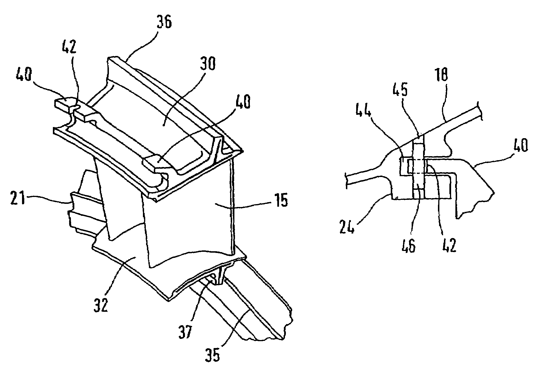
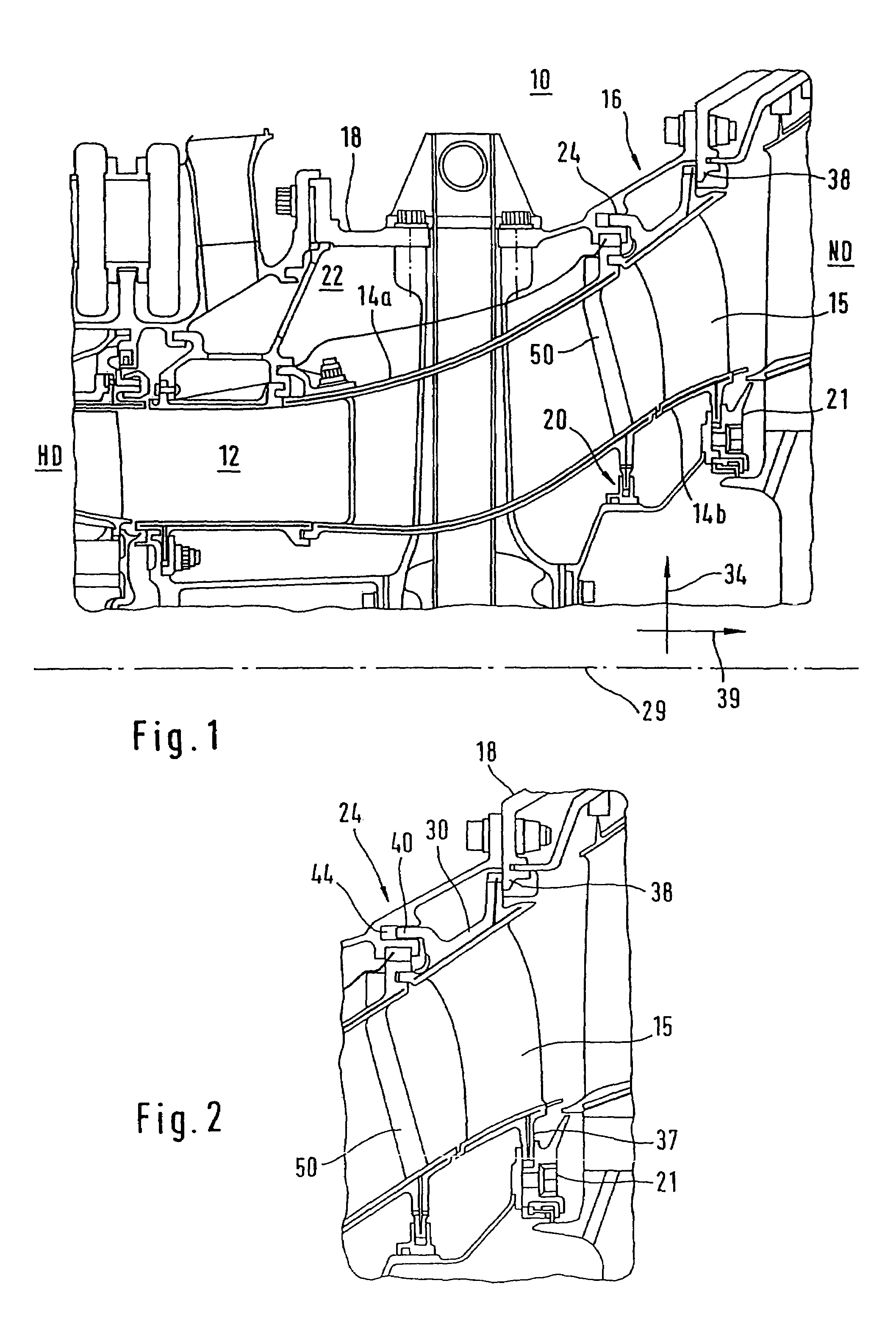
[0016]An aircraft gas turbine 10, which is shown only diagrammatically in FIG. 1 in the transition area between the high-pressure turbine HD and low-pressure turbine ND, contains a flow channel 12 designed as a ring channel, which leads from the small diameter of the high-pressure part HD to the larger diameter of the low-pressure part ND. This transition occurs via a transition channel 14, which comprises downstream a channel segment 14a and upstream a channel segment 14b of special design holding a plurality of guide blades 15, said segment being referred to in the following as a guide blade segment 16.

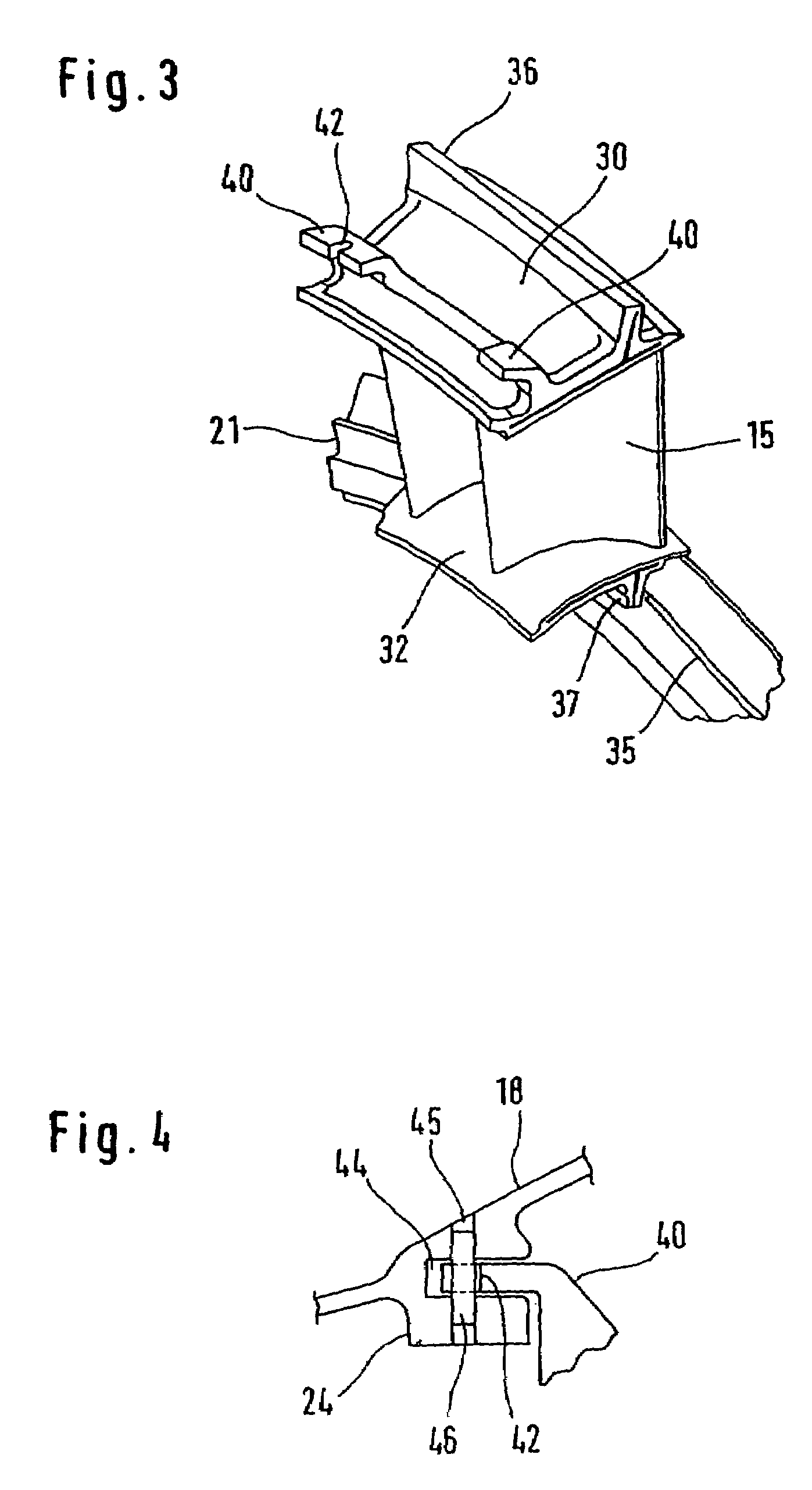
[0017]A housing, which overall has been designated with the number 18 and has a familiar structure, encloses the high and low-pressure parts of the turbine. Here the bearing pedestal 21 close to the seal 20 located in the channel intermediate space 22 as well as the bearing surfaces 24, 35 and 38 are of interest.

[0018]The guide blade segment 16 that bears the guide blades 15 compris...


PUM


Abstract

An arrangement for detachably fixing a guide blade segment that forms part of a transition channel of an aircraft gas turbine comprises high-pressure and low-pressure turbines. The arrangement has a groove-hook-type connection in the front area of the outer platform of the guide blade segment for its radial fixation and at least one pin that penetrates the hook-groove-type connection for securing it against rotation of the guide blade segment.

Description

BACKGROUND AND SUMMARY OF THE INVENTION[0001]This invention relates to an arrangement for fixing a guide blade segment that forms part of a transition channel.[0002]Modern aircraft gas turbines frequently comprise a so-called core engine with a high-pressure turbine having a relatively small diameter, which is arranged downstream from a low-pressure turbine having a relatively large diameter. This creates the necessity of transitioning the ring channel, which extends through the gas turbine and is equipped with guide blades, behind the high-pressure turbine from its small diameter to the large diameter of the low-pressure turbine, which occurs with the aid of a so-called transition channel.[0003]Such engines furthermore have high bypass ratios and low speeds of the low-pressure turbine shaft, which is generally separated in relation to the high-pressure turbine shaft; moreover the urgency exists to design the core engines in an increasingly compact and powerful manner, which leads t...

Claims


Application Information

Patent Timeline
Patent Type & Authority Patents(United States)
IPC IPC(8): F01D9/00F01D9/04F01D11/00
CPCF01D9/042F01D11/005Y02T50/671Y02T50/60
Inventor BOECK, ALEXANDER
Owner MTU AERO ENGINES GMBH
Why Eureka
Try Eureka