Method of manufacturing image display device

a technology of image display and manufacturing method, which is applied in the manufacture of image/pattern display tubes, electrode systems, tubes with screens, etc., can solve the problems of shortening the service life of the spacer, and affecting the installation accuracy of the device, etc., to achieve high accuracy and high accuracy. the effect of tension

Inactive Publication Date: 2007-08-21
CANON KK
View PDF15 Cites 7 Cited by
  • Summary
  • Abstract
  • Description
  • Claims
  • Application Information

AI Technical Summary

Benefits of technology

[0014]The present invention has been made in view of such conventional circumstances, and an object of the present invention is therefore to provide a method of manufacturing an image display device in which long spacers are efficiently joined between a pair of substrates with high accuracy by simultaneously gripping the spacers in an array of hands and simultaneously installing the spacers with high accuracy. The hands are paired and each pair grips both ends of one spacer. The hands apply a certain level of tension to the spacers. The hands on each end conform to surface irregularities of a face on which the spacers are to be placed, thereby minimizing a load that is in contact with the face on which the spacers are to be placed.
[0015]In order to attain the above object, a method of manufacturing an image display device according to the present invention relates to a method of manufacturing an image display device that has plural spacers for regulating a gap between a pair of substrates, including: gripping the plural spacers; and installing the gripped plural spacers on one substrate of the pair of substrates, characterized in that, in the gripping of the plural spacers, each of the plural spacers is gripped in a pair of hands with each hand of each pair gripping one end in a longitudinal direction of one spacer. Thus, each of the above requirements 1) through 4) are met and therefore it becomes possible to meet the requirement 5) concerning high precision installation.

Problems solved by technology

1) Both ends of a long spacer, which is a long, pliant object, are gripped.
2) The long spacer is given a certain level of tension.
3) The hands on both end sides of the long spacer conform to irregularities of a surface on which the long spacer is to be placed.
4) A load that is in contact with the surface on which the long spacer is to be placed is necessarily minimized.
5) A plurality of hands that meet the above requirements 1) through 4) are lined up to simultaneously grip a plurality of long spacers and install the long spacers at once with high accuracy (in a pitch direction).
The object gripping hands of the above-described prior art example fall short of satisfying the above requirements, and it is particularly difficult for the conventional hands to meet the requirement 5) concerning high precision installation.

Method used


Image

  • Method of manufacturing image display device
  • Method of manufacturing image display device
  • Method of manufacturing image display device

Examples


Embodiment Construction

[0032]An embodiment of a method of manufacturing an image display device in accordance with the present invention is described below with reference to FIGS. 1 to 16.

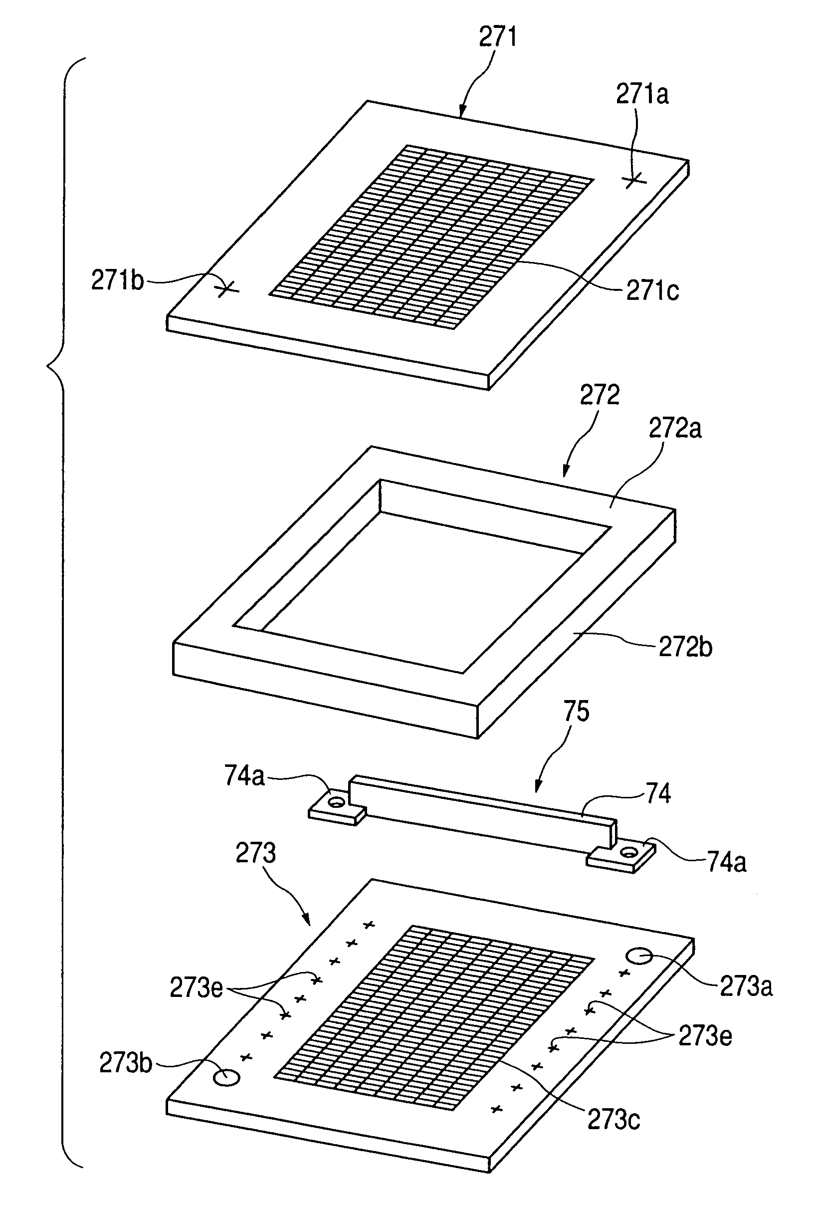
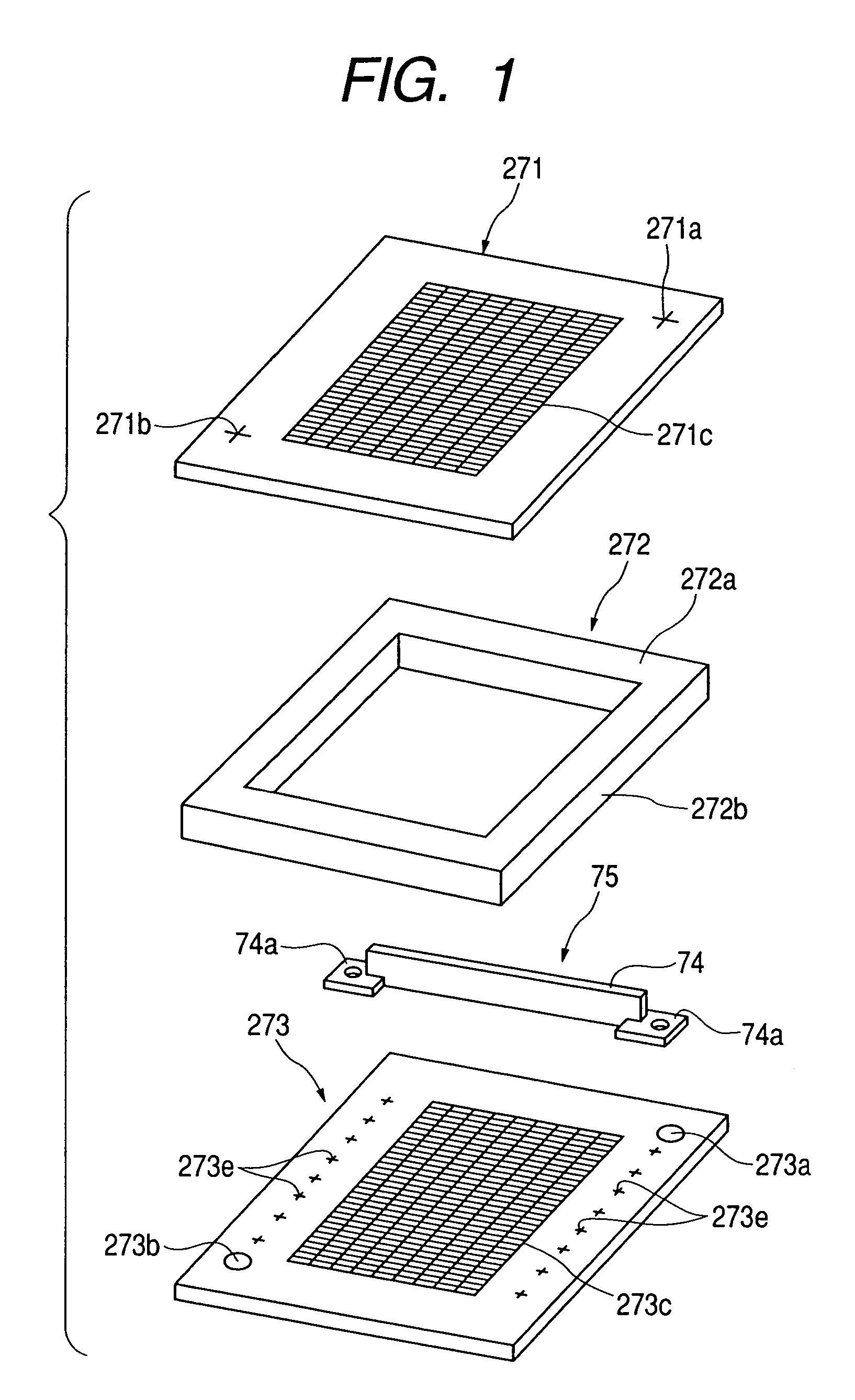
[0033]First, an image display device to be manufactured by the manufacture method according to this embodiment is outlined. This image display device has, as a pair of substrates (plates) facing each other, a rear plate on which electron-emitting devices form a matrix pattern and a face plate on which phosphors are formed at positions opposing the electron-emitting devices on the rear plate. The electron-emitting devices on the rear plate project electron beams at the opposing phosphors on the face plate, thereby causing the phosphors to emit light. The space between the plates in this image display device is in a vacuum and therefore spacers (long spacers) are provided to support the atmospheric pressure applied to the plates.

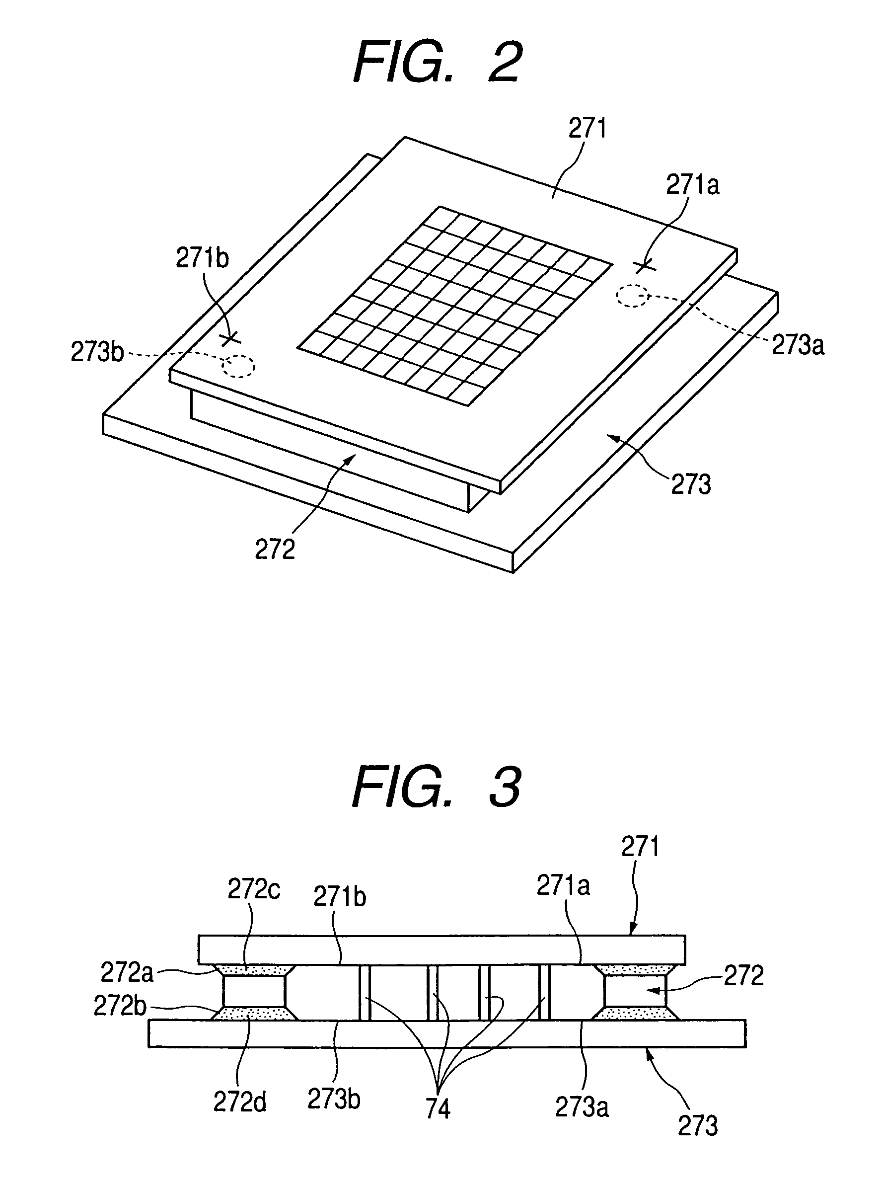
[0034]FIG. 1 is an exploded view of the image display device. FIG. 2 is a perspective view of t...


PUM


Abstract

A method of manufacturing an image display device, having a plurality of spacers for keeping a gap between a pair of substrates, includes the steps gripping each of the spacers at both ends in a longitudinal direction of each spacer, installing the plural spacers on one of the pair of substrates while exerting a tensile force to the gripped plural spacers, and applying an adhesive to the plural spacers installed on the one substrate, to tentatively fix by the adhesive the plural spacers to the one substrate. The adhesive is heated so that the plural spacers tentatively fixed to the one substrate are finally fixed to the one substrate.

Description

[0001]This application is a continuation of application Ser. No. 10 / 693,105, filed on Oct. 27, 2003 now U.S. Pat. No. 6,981,905 issued Jan. 3, 2006.BACKGROUND OF THE INVENTION[0002]1. Field of the Invention[0003]The present invention relates to a method of manufacturing an image display device and more specifically to a spacer installing method using a hand for gripping a long spacer in a method of manufacturing a flat panel display with a long spacer (atmospheric pressure support member) interposed between a pair of substrates (a face plate and a rear plate) that constitute a display panel.[0004]2. Description of the Related Background Art[0005]A conventional flat panel display has a pair of substrates (plates) composed of a face plate and a rear plate, and forms and displays an image by projecting electron beams, which are emitted from electron-emitting devices forming a matrix pattern on the rear plate side, at phosphors, which are formed on the face plate side. In this image dis...

Claims


Application Information

Patent Timeline
Patent Type & Authority Patents(United States)
IPC IPC(8): H01J9/00H01J9/24H01J9/26H01J31/12
CPCH01J9/241
Inventor YAKOU, TAKESHIMACHINO, MASAKIYAMAGUCHI, TAKEHITO
Owner CANON KK
Why Eureka
Try Eureka