Device and method for low pressure compression and valve for use in the system

a low-pressure compression and valve technology, applied in the field of self-powered compression devices and methods, can solve the problems of lack of control of adjustability, difficulty in application and removal, and varying degrees of shortcomings, and achieve the effect of accurate control of air pressure and affordable cos

Inactive Publication Date: 2007-08-21
C BOOT
View PDF31 Cites 68 Cited by
  • Summary
  • Abstract
  • Description
  • Claims
  • Application Information

AI Technical Summary

Benefits of technology

[0011]The pneumatic control system of the invention creates a cycle of air flow by closing the exhaust valve in each sleeve, allows air to fill the sleeve through the inlet valve to a pretuned pressure, and finally deflates the sleeve by letting the air flow through the outlet valve. This creates a pressure gradient that facilitates the massaging movement on the limb towards direction of the heart.
[0016]In another embodiment of the present invention, the magnetic valve provides an accurate control of the air pressure by detecting very low pressure changes in the range of about 15 mmHg, for example, in compression devices using low pressures such as in vascular pumps, pneumatic walking devices, weather forecast equipment or vacuum-based equipment, all at an affordable cost.
[0017]In a preferred embodiment of the present invention the magnetic power of the magnetic ring is sufficiently strong so that when the magnetic ring is separated from the metal ball, the magnetic attraction between the magnetic ring and the metal ball reduces by a factor of square (X2) in relation to the distance between the magnetic ring and the metal ball.

Problems solved by technology

Most suffer varying degrees of shortcomings, including ineffectiveness, difficulties in application and removal, lack of controlled adjustability, loss of compression, excessive sweating, foul odor and discomfort.
Some of the disadvantage of this system are: 1) it is not adapted to regulate low-pressure changes 2) it is not automatic 3) it is not tunable and 4) it is not sequential.
However, the device described in the above patent is not adapted to control and regulate low-pressure changes, and therefore optimal performance is not achieved.

Method used


Image

  • Device and method for low pressure compression and valve for use in the system
  • Device and method for low pressure compression and valve for use in the system
  • Device and method for low pressure compression and valve for use in the system

Examples


Embodiment Construction

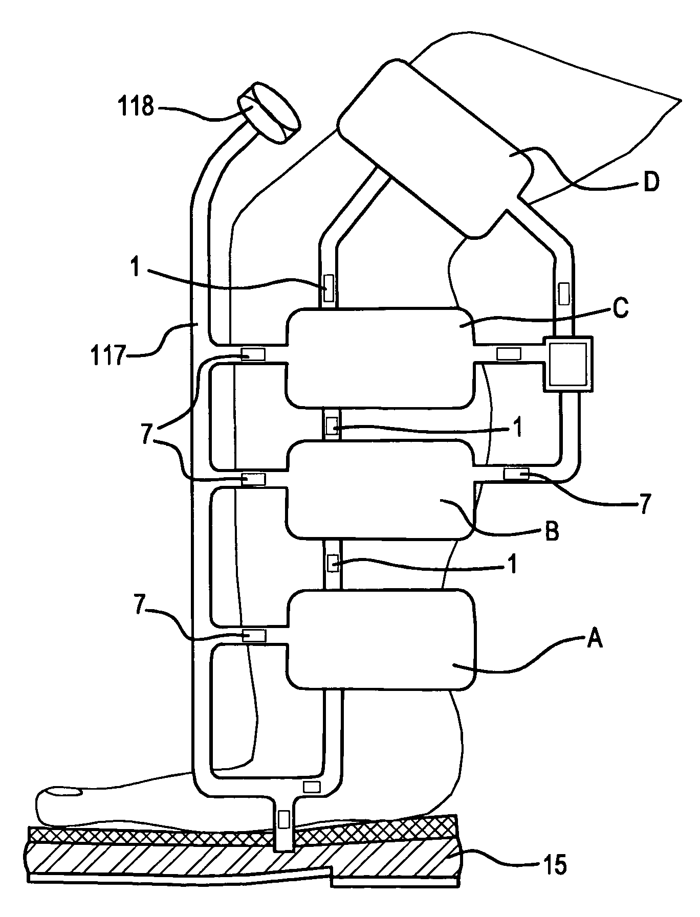
[0023]The present invention provides a pneumatic pressure control system that operates in sequential pressure cycles. For example, each cycle starts when the wearer takes a step, atmospheric air enters the system, pressure increases, this seals the exhaust valves and allows the first sleeve to fill up through a tunable inlet valve. Then the second sleeve starts to fill to a tunable pressure, and so on until the pressure reaches a preset level in each sleeve. This is then followed by activating the relief valve and opening the exhaust valves to allow deflation of air from the sleeves.

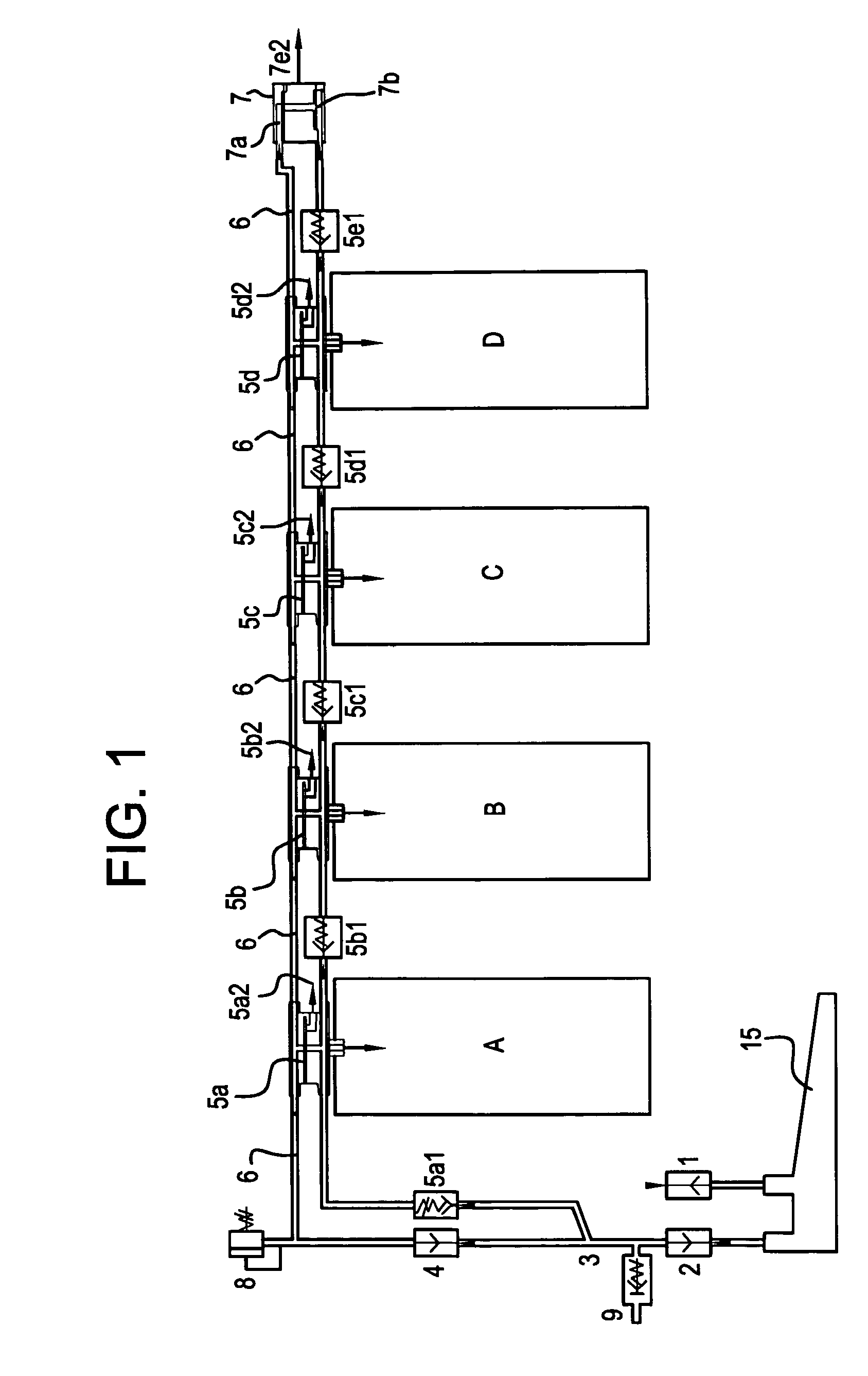
[0024]FIG. 1 describes a system, wherein the pressure of each individual inter-connected chamber is higher than the pressure in the chamber immediately above, or superior to, and less than the pressure in the chamber immediately below, or inferior to, said individual chamber.

[0025]In FIG. 1, the atmospheric air is pumped into the foot pump through the inlet valve 1. The foot pump 15 compresses the air in...


PUM


Abstract

The present invention relates generally to compression devices and, more particularly to a method using air flow to close the exhaust valve in each sleeve, allows air to fill the sleeve to a pretuned pressure, and finally deflating the sleeve by letting the air flow through the outlet valve. This creates a pressure gradient and a pneumatic cycle means that facilitates the massaging movement on the limb towards direction of the heart. The magnetic force in valves is uniquely adapted for controlling low-pressure compression. A magnetically adjustable valve is adapted for use in a compression device to control and regulate low to very low pressures and comprising of a movable magnetic part and a metal part, defining an air gap there between. A self-powered device causes the magnetic part and the metal part to move away from each other and control the air access and pressure in the valve body, while creating a gradient of decreasing pressure, the highest pressure being in the first air chamber to the lowest pressure in the last air chamber.

Description

CROSS-REFERENCE TO OTHER APPLICATION[0001]This application is a Continuation-in-part of Provisional application Ser. No. 60 / 477,656, filed on Jun. 11, 2003, which in turn is a Continuation-in-Part of application Ser. No. 09 / 602,224, filed Jun. 23, 2000, and issued as U.S. Pat. No. 6,589,194 on Jul. 8, 2003, which references are all incorporated herein in its entirety.FIELD OF THE INVENTION[0002]The present invention relates to self-powered compression devices and methods for promoting circulation by applying low pressure compression. It is a self-powered system driven by atmospheric air drawn into the system at every step. More particularly, the invention is in the class of medical devices, comprising an inlay legging, a plurality of sleeves or balloons, which utilize sequential, cyclical pressure to aid circulation in a body part such as the limb of a mammal. The present invention relates generally to compression devices and, more particularly, to a method and device for low pressu...

Claims


Application Information

Patent Timeline
Patent Type & Authority Patents(United States)
IPC IPC(8): A61F5/00A61HA61H23/04
CPCA61H9/0078A61H9/0085A61F5/00A61H7/00A61H9/00
Inventor CALDERON, NOAM A.DROR, AMIT BEN
Owner C BOOT
Why Eureka
Try Eureka