Medical punch and surgical procedure

a medical and surgical technology, applied in the field of medical punches, can solve the problems of device jamming with vessel tissue, inconvenient screwing of punches, and inability to clean and accurate the cut thus produced, and achieve the effects of convenient scissor-like shearing action, clean and accurate cut of vessel tissues, and convenient screwing

Inactive Publication Date: 2007-08-21
MAQUET CARDIOVASCULAR LLC
View PDF82 Cites 58 Cited by
  • Summary
  • Abstract
  • Description
  • Claims
  • Application Information

AI Technical Summary

Benefits of technology

[0010]In accordance with one embodiment of the present invention a medical punch has a helical leading edge that facilitates screwing the punch into a pressurized vessel without having to make a separate incision or using a clamp, and the helical leading edge serves as a helical cutting edge that facilitates scissor-like shearing action. The punch includes a hollow body member, the end of which provides a mating cutting edge. A shaft located within the hollow bod...

Problems solved by technology

Because the conventional medical punch accomplishes cutting of tissue by shearing, and effects this shearing by sliding a cutting edge past the anvil, the vessel tissue does not remain centralized and may shift slightly during the cut, and the cut thus produced is not always clean and accurate because some fraying may result.
Additionally, because the vessel tissue does not remain centralized and shifts during the cutting operation, the vessel tissue has a tendency to gather to one side or the other of the anvil of the device.
This often causes the device to become jammed with vessel tissue.
This can result in problems if the incision is not large enough.
Inserting the anvil into this small incision can result in tearing of the vessel tissue, and in difficulty operating the punch if the anvil must be awkwardly forced into position.
The anvil can be more easily inserted if the incision is too large, but the procedure may result in leakage around ...

Method used


Image

  • Medical punch and surgical procedure
  • Medical punch and surgical procedure
  • Medical punch and surgical procedure

Examples


Embodiment Construction

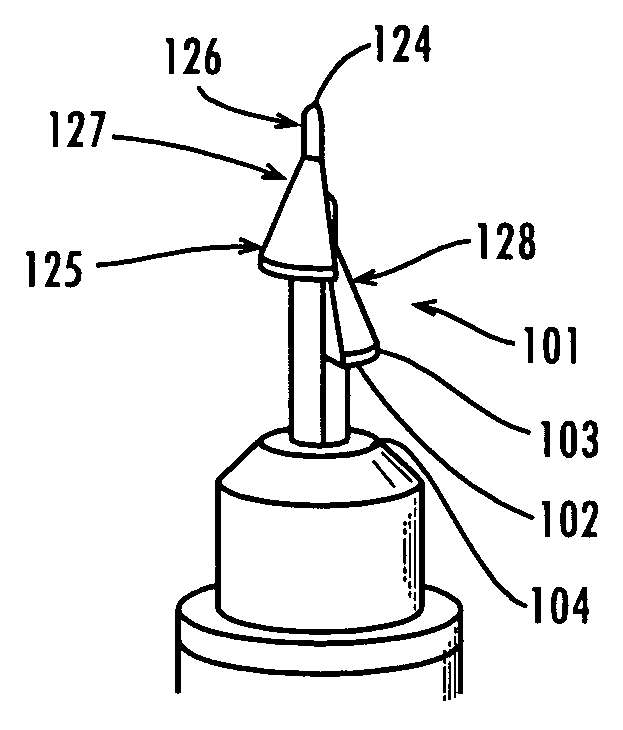
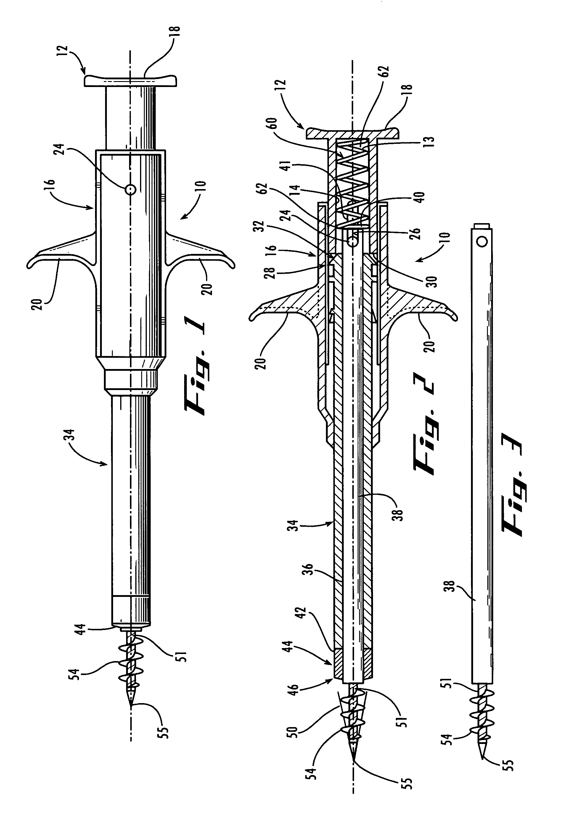
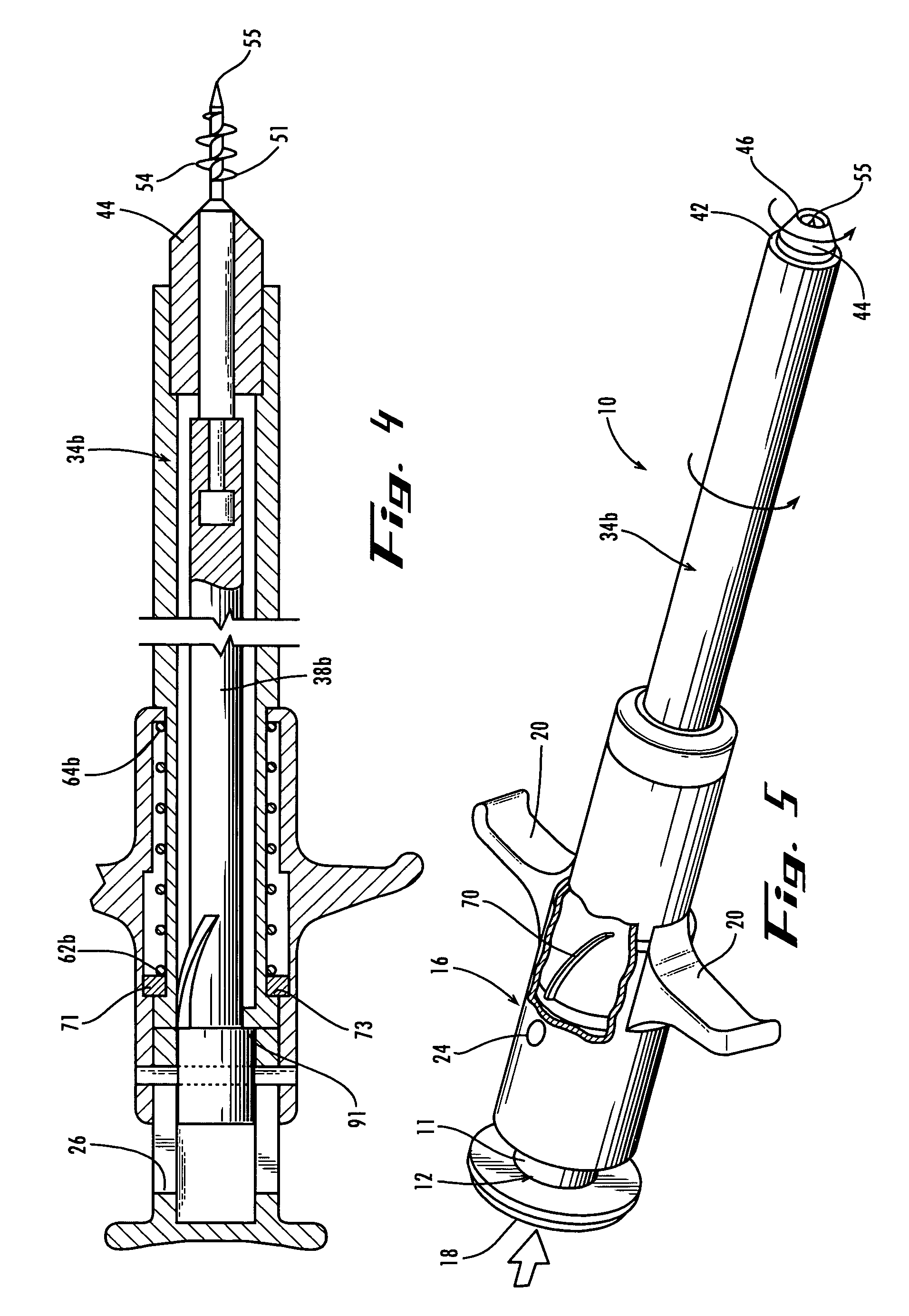
[0041]Referring now to FIGS. 1 and 2, there is shown one embodiment of a medical punch 10 in accordance with the present invention. Instead of having a single cutting edge with effectively no shear angle, the medical punch 10 includes a screw-like anvil with a helical cutting edge 54 that cooperates with the cutting edge 44 at the end of the hollow body member 34 to create a scissor-like shearing action around the perimeter of cutting edge 44. As a result, the medical punch 10 can be used to achieve a clean and accurate cut of vessel tissue. Additionally, the medical punch 10 eliminates the need for excessive hand pressure to effect the shearing of tissue which progresses along the helical edge 54 in response to the cutting edge 44 sliding over the helical edge 54. In addition, the helical edge 54 facilitates augering the anvil 51 into the wall of a vessel such as the aorta carrying blood under pressure without having to make a separate initial incision or having to clamp off the ve...


PUM


Abstract

A medical punch includes a longitudinally dividable anvil with a reduced cross-sectional dimension facilitating insertion of the anvil into the vessel wall to achieve a clean aperture in the vessel wall by cooperative shearing action of a cutting edge and an anvil edge. In another embodiment, the instrument incorporates a measuring device for determining the thickness of a vessel wall between an anvil and a distal end of a cylindrical structure which together form a caliper, and the measuring device can also constitute a medical punch by cooperative shearing action of a cutting edge and an anvil to achieve a clean aperture in the vessel wall.

Description

RELATED APPLICATIONS[0001]This application is a continuation-in-part of the U.S. patent application Ser. No. 10 / 173,997, entitled “Medical Punch and Surgical Procedure” filed on Jun. 17, 2002, which subject matter is incorporated herein by this reference to form a part hereof.FIELD OF THE INVENTION[0002]This invention relates to medical punches and more particularly to a split anvil punch for cutting a clean aperture in vessel tissue, and a measuring device for determining the thickness of the vessel wall.BACKGROUND OF THE INVENTION[0003]Medical punches are used in certain surgical procedures to cut tissue. For example, a blood vessel is cut using a medical punch, and surgical scalpels and / or scissors are first used to form an incision in the vessel. Typically, the medical punch includes an anvil which is first inserted into the incision. Then, a tube of the medical punch extends, and a cutting edge of the tube slides along the anvil, thus shearing the vessel tissue. Finally, the an...

Claims


Application Information

Patent Timeline
IPC IPC(8): A61B17/32A61B17/3209
CPCA61B17/32053A61B2017/00778A61B2017/22034A61B2019/461A61B2090/061
Inventor CHOI, STEVENREED, SCOTTBACHMAN, ALAN
Owner MAQUET CARDIOVASCULAR LLC
Why Eureka
Try Eureka