Method and apparatus for aggregating power from multiple sources

a technology of power aggregation and power supply, applied in the direction of pulse technique, emergency protective arrangement for limiting excess voltage/current, transportation and packaging, etc., can solve the problems of limiting the maximum power drawn, the resistance of the line may be large, and the current may be further limited, so as to limit the maximum power drained and the resistance of the line large

Active Publication Date: 2007-08-21
F POSZAT HU
View PDF30 Cites 188 Cited by
  • Summary
  • Abstract
  • Description
  • Claims
  • Application Information

AI Technical Summary

Benefits of technology

[0010]By way of introduction, the preferred embodiments below provide a method and apparatus for aggregating power from multiple sources. The apparatus generates a single direct current regulated voltage for powering a load. The apparatus is connected to a plurality of direct current power sources by a plurality of lines. Each direct current power source has an open circuit voltage. The open circuit voltage may be unknown, although the maximum open circuit voltage is known. Each line of the plurality of lines has a line resistance. The line resistance may be unknown. Furthermore, the line resistance may be large. Current is drawn from the power sources through the plurality of lines. The apparatus generates the single direct current regulated voltage from the drawn current. For each line, the current drawn is limited such that a closed circuit voltage corresponding to a voltage across the line while drawing the current is at least one half of the open circuit voltage. The current may be further limited such as to limit the maximum power drawn from each power source. The apparatus comprises a master pulse width modulator circuit and a plurality of slave voltage converters. The master pulse width modulator circuit produces a master pulse width modulated signal. Each slave voltage converter of the plurality of slave voltage converters is connected to a line of the plurality of lines. Each slave voltage converter receives the master pulse width modulated signal. Each slave voltage converter is operative to modify the master pulse width modulated signal such as to maintain the voltage relationship between the open circuit voltage and the closed circuit voltage, and to limit the maximum power drained from the power source connected to the slave voltage converter. Each slave voltage converter uses the master pulse width modulated signal to switch the drawn current through a power stage. The power stage produces an output voltage. Many different power stages may be implemented. The output voltages of all of the plurality of slave voltage converters are conjoined to form the single direct current regulated voltage.

Problems solved by technology

Furthermore, the line resistance may be large.
The current may be further limited such as to limit the maximum power drawn from each power source.

Method used


Image

  • Method and apparatus for aggregating power from multiple sources
  • Method and apparatus for aggregating power from multiple sources
  • Method and apparatus for aggregating power from multiple sources

Examples


Embodiment Construction

[0019]In the figures described in the specification, the same reference characters refer to the same parts throughout the specification and drawings.

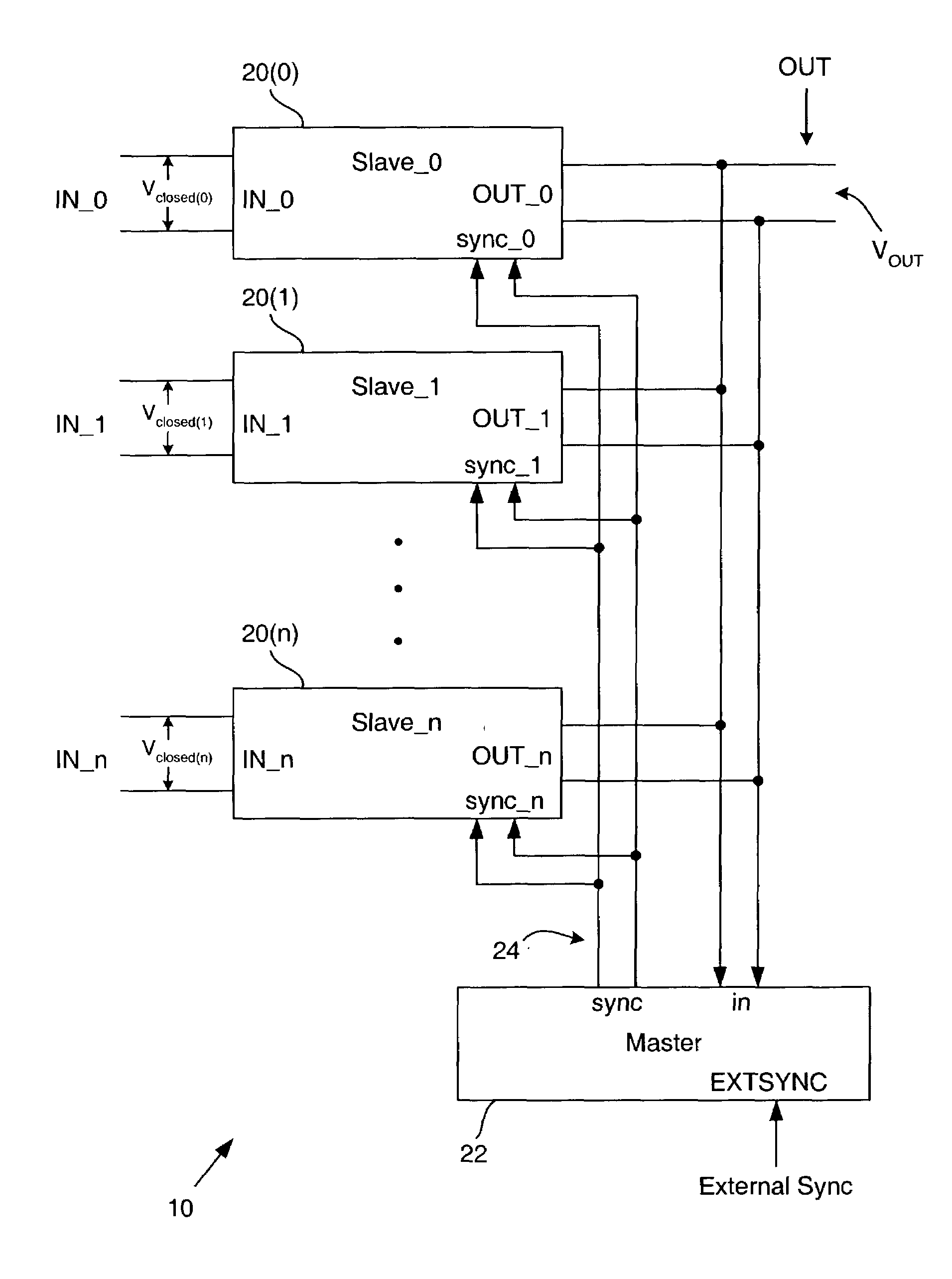
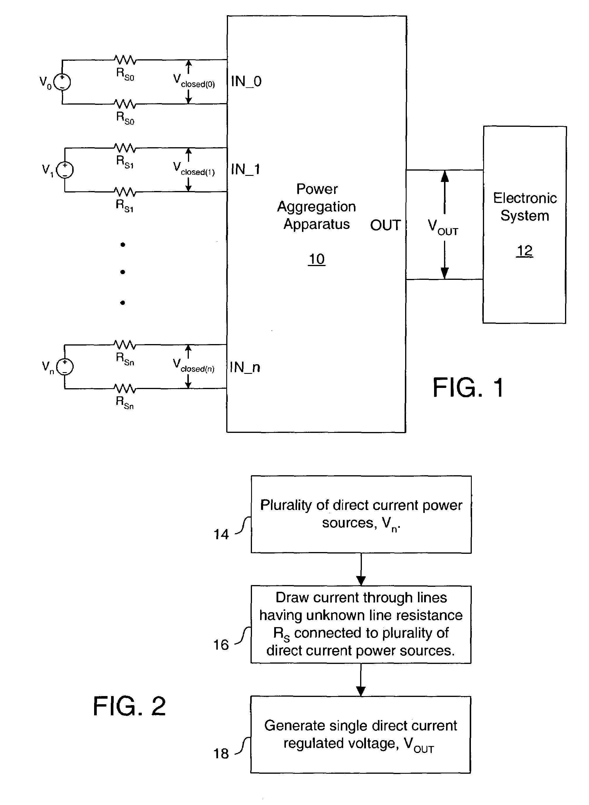
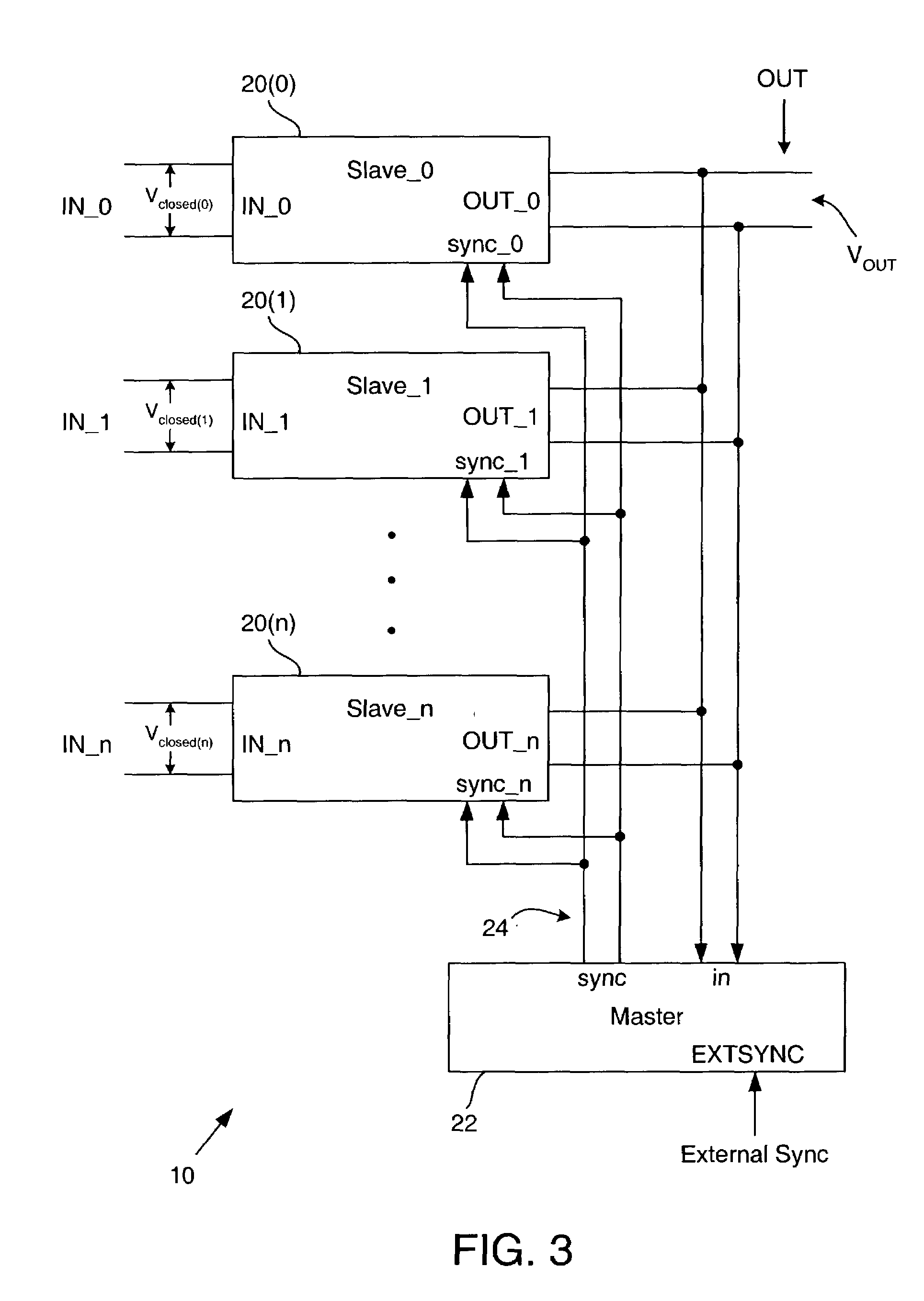
[0020]Referring to FIG. 1, a power aggregation apparatus 10 is shown. The power aggregation apparatus 10 comprises a plurality of inputs, IN_0 through IN_n, and an output, OUT. The inputs are connected to a plurality of direct current power sources, V0 through Vn, by a plurality of lines. Each line of the plurality of lines has a line resistance shown by the resistors RS0 through RSn. The output, OUT, is connected to an electronic system 12. Briefly, the power aggregation apparatus 10 draws current from the power sources, through the lines, and generates a single direct current regulated voltage, Vout, on the output, OUT. The term “line” is understood to include a wire pair and therefore may be used interchangeably with the term “wire-pair.”

[0021]The line resistance RSn of at least some of the lines may be unknown. Furthermore, the line...


PUM


Abstract

A method and apparatus for aggregating power from multiple sources generates a single direct current regulated voltage. The apparatus comprises a plurality of slave voltage converters and a master pulse width modulator circuit. Providing a plurality of direct current power sources, current is drawn through a plurality of lines connected to the plurality of direct current power sources. An open circuit voltage for each direct current power source is unknown. Each line of the plurality of lines has a line resistance. The line resistance of at least some of the plurality of lines may be unknown. The line resistance of at least some of the plurality of lines is large. The single direct current regulated voltage is generated from the drawn current.

Description

BACKGROUND[0001]When powering an electronic system, close attention must be paid to the power source or sources and how best to deliver power from the power sources to the electronic system. Almost all power sources have a limited capacity to supply power to a load. A power source has limitations determined by its generator and a transmission line connecting the generator to the load, or electronic system.[0002]Typically, an electronic system is designed having a power specification. A power system is designed that meets the needs of the power specification of the system. In designing the power system, the transmission line between the load and the generator is sized such that power is transferred with an acceptable level of loss and that sufficient power reaches the load. The generator is specified to be capable of supplying the load power plus the transmission line losses.[0003]In the case of telecommunication systems, such as the public switched telephone network (PSTN), there ex...

Claims


Application Information

Patent Timeline
Patent Type & Authority Patents(United States)
IPC IPC(8): H02J3/38H02J1/10H02J3/06
CPCH02J1/10H02J1/102
Inventor BLANC, JAMES JOSEPH
Owner F POSZAT HU
Why Eureka
Try Eureka