Method and device for imaging of a printing form

a printing form and imaging technology, applied in the field of imaging a printing form, can solve the problems of occupying a rather large space, occupying a longer average life, and limited to a power range below 1 wa

Inactive Publication Date: 2007-08-21
HEIDELBERGER DRUCKMASCHINEN AG
View PDF7 Cites 4 Cited by
  • Summary
  • Abstract
  • Description
  • Claims
  • Application Information

AI Technical Summary

Benefits of technology

[0015]A further or alternative object of the present invention is to provide an improved method and an improved device for imaging a printing form which prevent imaging errors during use thereof.
[0017]A method according to the present invention for imaging a printing form, in which a laser generates a sequence of pulses of electromagnetic radiation corresponding to the image information of an image area to be generated on the printing form, and the image area to be generated on the printing form is patterned according to the image information by interaction with the electromagnetic radiation, has the feature that the sequence of pulses of electromagnetic radiation is amplified by an amplifier; the amplifier being discharged in a controlled manner by additional pulses corresponding to a non-image area of the printing form in such a way that interference pulses of the amplifier are prevented.
[0020]In accordance with the present invention, the imaging pulse sequence is amplified; the amplifier being discharged as a precautionary measure by additional pulses in gaps of the imaging pulse sequence. The discharging of the amplifier effectively prevents self-excitation of interference pulses in the amplifier. In this connection, the gaps in the imaging pulse sequence correspond to non-image areas, such as the area of the cylinder gap.
[0022]By using the method of the present invention, it is possible to prevent interference pulses, such as self-q-switched pulses. Before the amplifier, for example, a laser-pumped fiber amplifier, has accumulated enough energy to independently generate an interference pulse, the energy stored in the amplifier is removed as a precautionary measure and deposited in an area that is not used for the production of a printed product.
[0026]In accordance with the present invention, the image information, which usually contains image data for the image areas and gaps for the non-image areas, may be supplemented with additional data, preferably in the gaps. Although the gaps represent non-image areas, these gaps are usable according to the present invention. Activation of the imaging device in the gaps, i.e., in non-image areas, can be advantageously used to activate the imaging device without affecting the product to be printed. In this manner, for example, an amplifier can be discharged without effect while imaging is in progress.
[0028]A device according to the present invention for imaging a printing form, including a laser which generates a sequence of pulses of electromagnetic radiation corresponding to the image information of an image area to be generated on the printing form; the image area to be generated on the printing form being patterned according to the image information by interaction with the electromagnetic radiation, features an amplifier which amplifies the sequence of pulses of electromagnetic radiation, and a unit which generates additional pulses corresponding to a non-image area of the printing form; the additional pulses discharging the amplifier in a controlled manner such that interference pulses of the amplifier are prevented.

Problems solved by technology

For this reason, the lasers usually used for laser imaging are gas lasers, such as argon-ion lasers or helium-neon lasers, which, however, occupy a rather large space.
Also known from the prior art are less expensive lasers requiring much less space, such as diode lasers which, in addition, have a longer average life, but are mostly limited to a power range below 1 watt.
Therefore, such an amplifier system cannot be used so easily for imaging printing forms because here, depending on the image information, for example, in the case of extensive non-printing areas which extend, in particular, in the circumferential direction, no imaging spot is to be produced during certain periods of time, and therefore, the fiber amplifier is not discharged by a signal of the imaging laser.
Given a sufficiently long period of time, a self-q-switching effect can occur, as mentioned above, so that the fiber emits a signal independently, i.e., by self-excitation, which may lead to unwanted imaging in the form of an imaging spot, or destroy the output facet of the fiber.

Method used


Image

  • Method and device for imaging of a printing form
  • Method and device for imaging of a printing form
  • Method and device for imaging of a printing form

Examples


Embodiment Construction

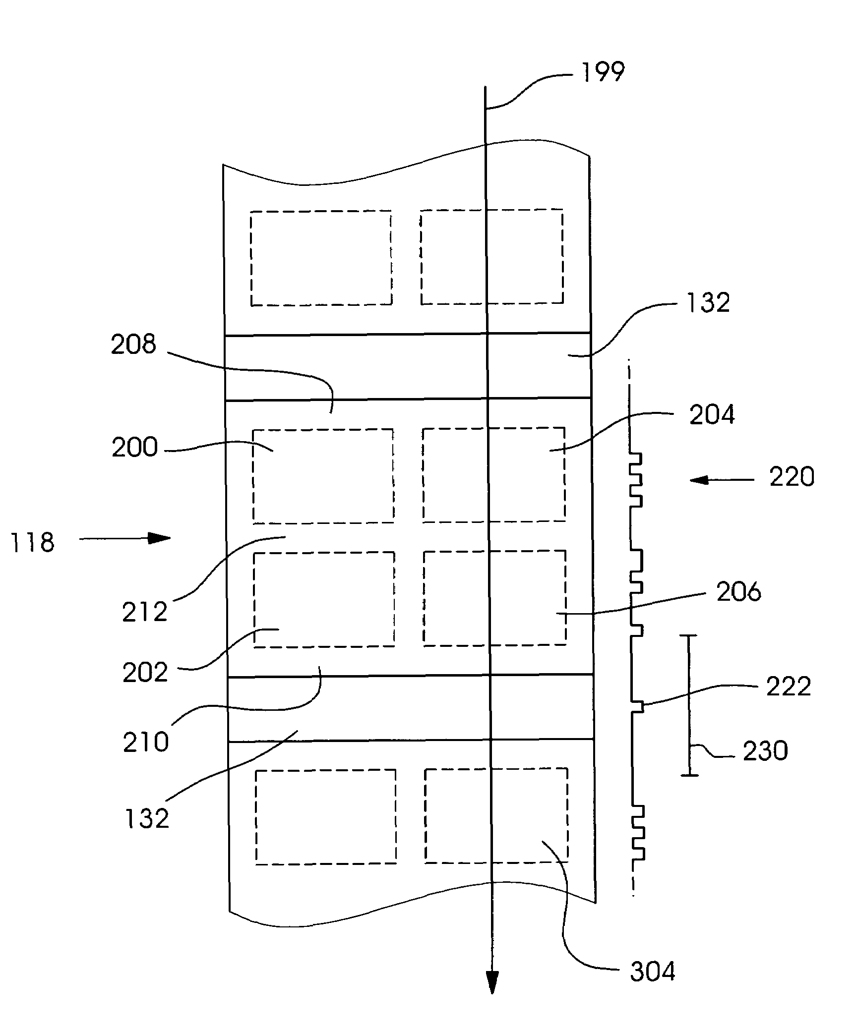
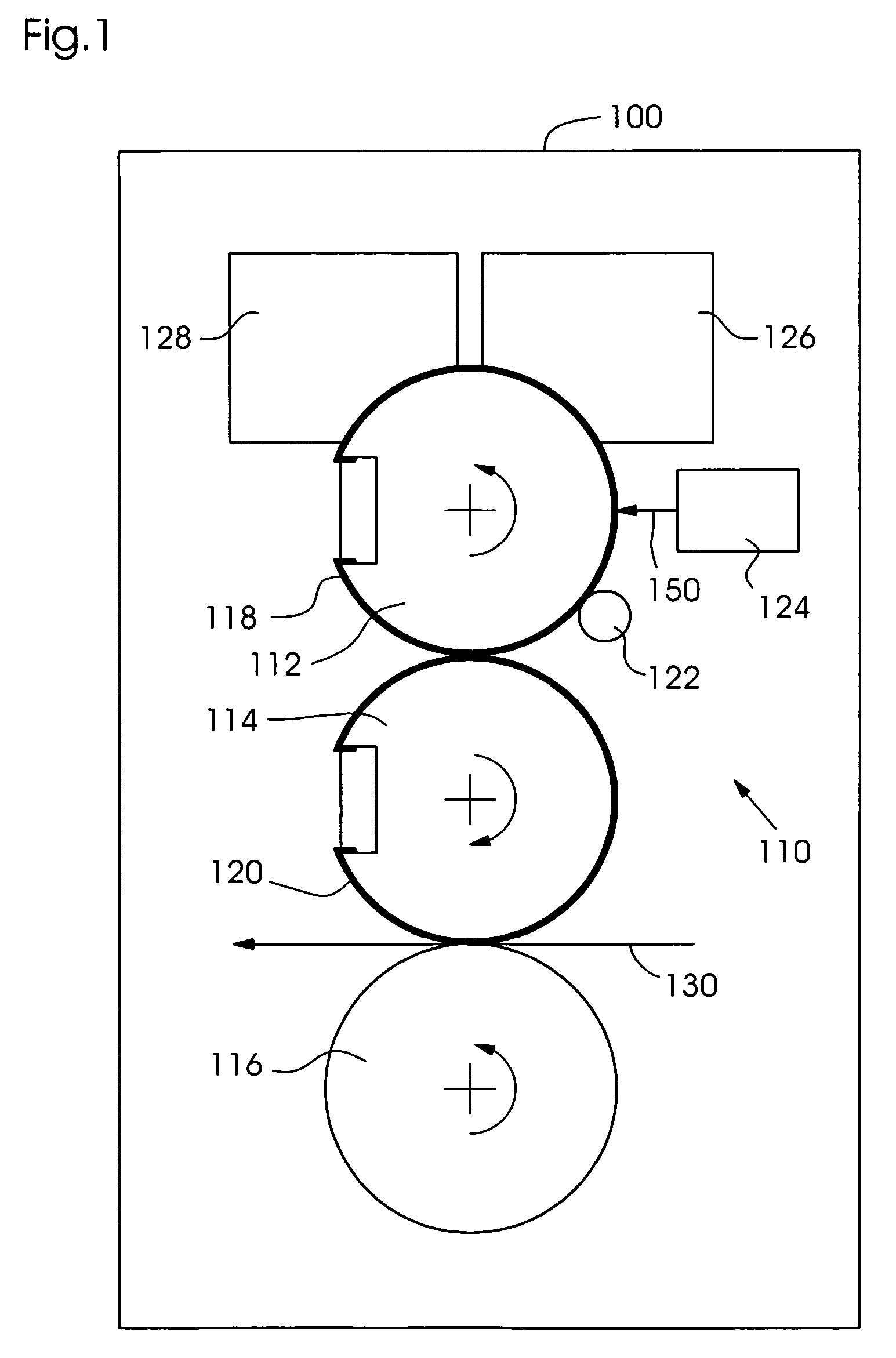
[0039]FIG. 1 shows a printing-material processing machine 100, here, in particular, a sheet-fed offset printing press. A printing unit 110 of the printing press is associated with a plate cylinder 112, a transfer cylinder 114, and an impression cylinder 116; a printing form in the form of an offset printing plate 118 being mounted on the surface of plate cylinder 112, and a rubber blanket 120 being mounted on the surface of transfer cylinder 114. Offset printing plate 118 is designed as an imagable or, possibly, reimagable printing plate.

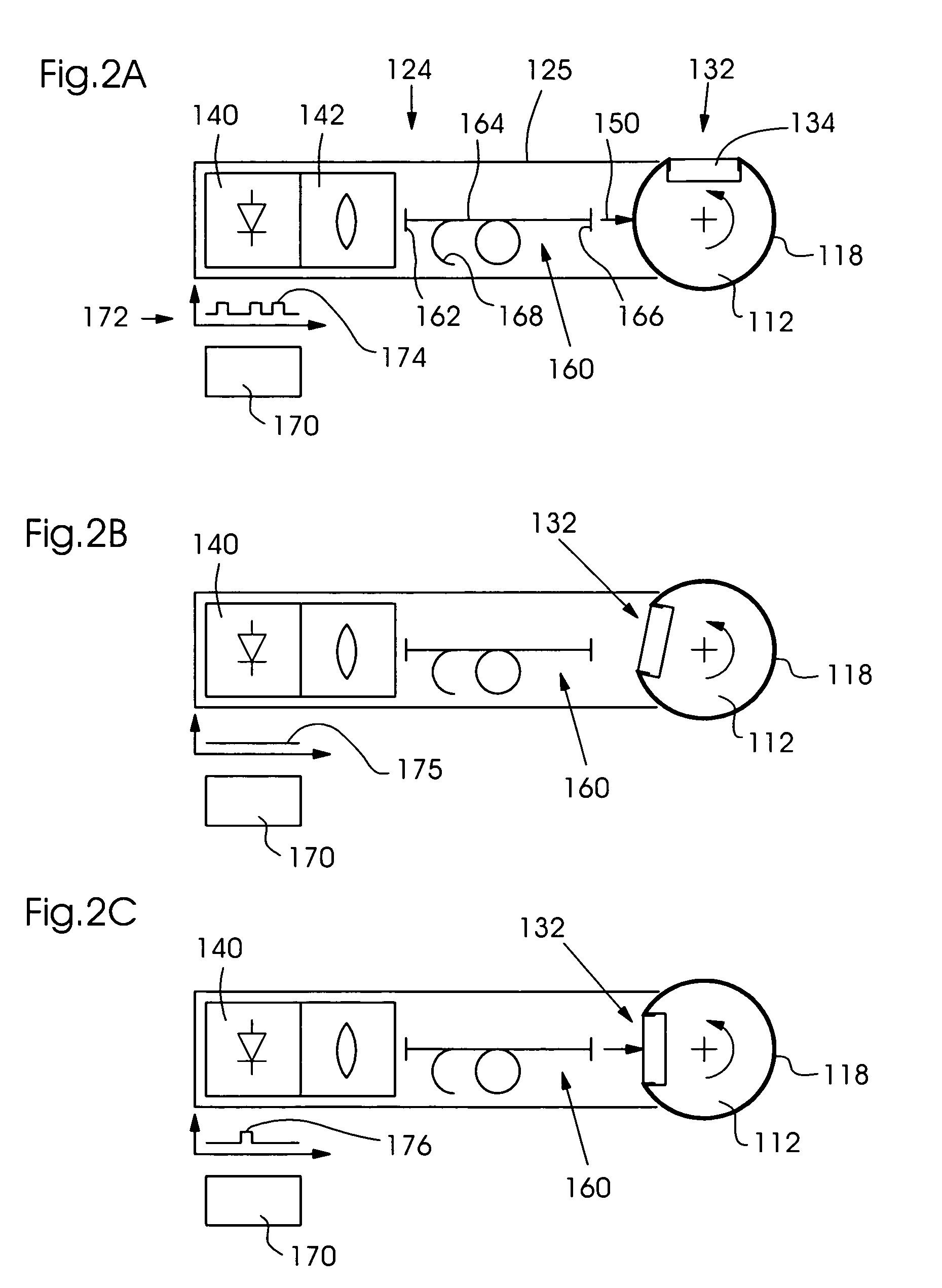
[0040]A cleaning device 122, an inventive imaging device 124, a dampening system 126, and an inking system 128 are arranged along the circumference of plate cylinder 112. In an imaging mode, imaging device 124 generates a laser beam 150, which patterns the surface of printing plate 118 according to the image information. Imaging device 124 can be moved, for example, in an axial direction relative to the axis of the plate cylinder in order to complet...


PUM

PropertyMeasurementUnit
poweraaaaaaaaaa
diameteraaaaaaaaaa
surface speedaaaaaaaaaa

Abstract

A method for imaging a printing form, in which a laser (140) generates a sequence of pulses (172, 220) of electromagnetic radiation corresponding to the image information of an image area (200, 202, 204, 206) to be generated on the printing form (118), and the image area (200, 202, 204, 206) to be generated on the printing form (118) is patterned according to the image information by interaction with the electromagnetic radiation, has the feature that the sequence of pulses (172, 220) of electromagnetic radiation is amplified by an amplifier (160); the amplifier (160) being discharged in a controlled manner by additional pulses (176, 222) corresponding to a non-image area (132, 208, 210, 212) of the printing form (118) in such a way that interference pulses of the amplifier (160) are prevented.

Description

[0001]This claims the benefit of German Patent Application No. 103 57 432.8, filed Dec. 9, 2003 and hereby incorporated by reference herein.BACKGROUND INFORMATION[0002]The present invention relates to a method for imaging a printing form. The present invention is also directed to a device for imaging a printing form.[0003]When imaging printing plates capable of being imaged once or multiple times, printing sleeves, printing belts, or printing cylinder surfaces (in this patent application generally referred to as “printing form” hereinafter), the image data for the print job is processed by a raster image processor (RIP), and usually provided to a laser imaging device (mostly using an infrared laser), which transfers or writes the data as image information to the surface or into an upper layer of the printing form in the form of a pattern.[0004]For this purpose, the prior art has disclosed offline imaging devices (such as plate setters) using the internal drum, external drum, or flat...

Claims


Application Information

Patent Timeline
Patent Type & Authority Patents(United States)
IPC IPC(8): G03F7/20B41J2/435B41C1/055B23K26/00B41C1/00B41C1/05B41F7/02B41M5/00G03G13/00G03G15/00H04N1/036H04N1/38
CPCB41C1/05B41P2227/70
Inventor BEIER, BERNARD
Owner HEIDELBERGER DRUCKMASCHINEN AG
Why Eureka
Try Eureka