Network system using management frames for supervising control units

Inactive Publication Date: 2007-08-21
DENSO CORP
View PDF19 Cites 22 Cited by
  • Summary
  • Abstract
  • Description
  • Claims
  • Application Information

AI Technical Summary

Benefits of technology

[0014]Thus, in this network system, operating contents need not be recorded in every control unit in order to specify the abnormality cause of the control unit, and the construction of each control unit can be simplified. Besides, since an analytical operation for specifying the abnormality cause is unnecessary, a job for improving or repairing the system by specifying the abnormality cause can be carried out very efficiently.

Problems solved by technology

Thus, a communication abnormality is intentionally incurred upon the occurrence of the power source abnormality.
However, neither of the related techniques can specify the cause of the abnormality.
Therefore, in a case where any specified control unit continues to operate due to a malfunction in spite of a state in which the controlled device has stopped its operation, so that all the control units constituting the network system ought to stop their operations, or in a case where any control unit repeats starts and stop due to a malfunction, although the malfunctioning control unit itself can be specified by applying the former system, a long time is expended in specifying the cause of the malfunction and then improving the system.
In this case, especially when the abnormality cause of the control unit is a very infrequent abnormality cause which arises in a single-shot manner under exceptional conditions, the abnormality cause cannot be specified and hence the system cannot be improved by specifying the abnormality cause.
However, the quantity of data to be stored becomes enormous in a system whose control is complicated as in the automobile.
Further, it is difficult to specify the abnormality cause from among the data of the enormous control contents in a short time, so that such a method cannot be adopted.

Method used


Image

  • Network system using management frames for supervising control units
  • Network system using management frames for supervising control units
  • Network system using management frames for supervising control units

Examples


Embodiment Construction

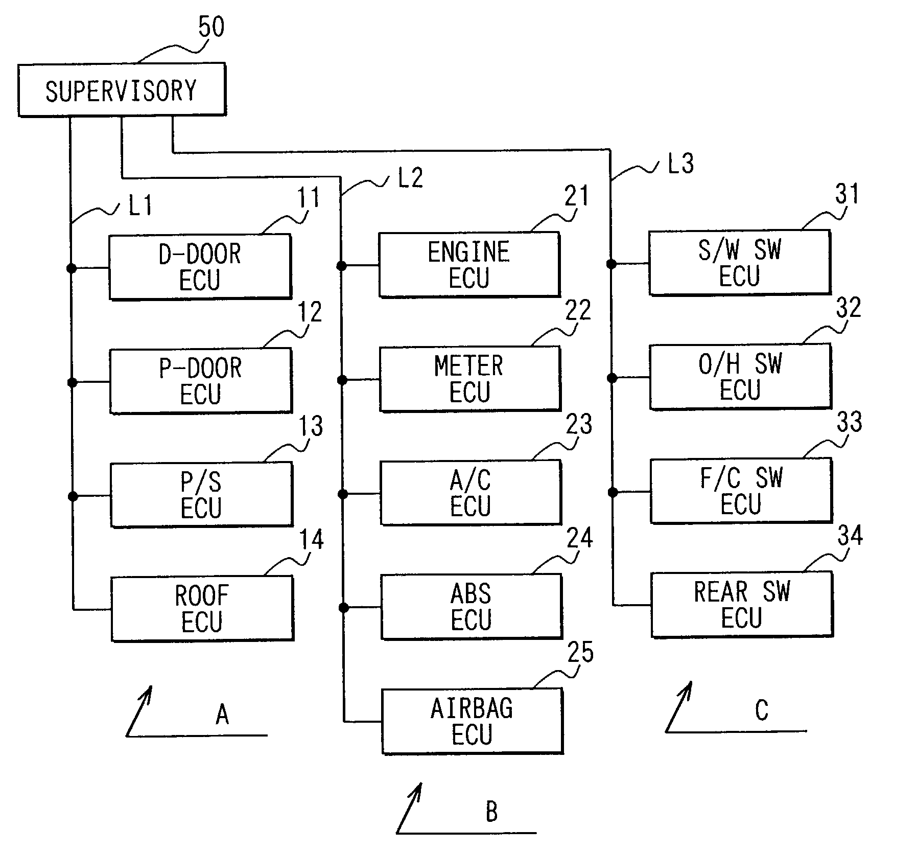
[0025]Referring to FIG. 1, a network system according to this embodiment is applied to a body system of an automobile. The network system includes a plurality of networks A, B and C. The networks A, B and C include electronic control units (ECUs) 11-14, 21-25 and 31-34 as control units which are disposed for controlled devices (vehicle constituents). The networks A, B and C also includes communication lines L1, L2 and L3 to which the corresponding ECUs 11-14, 21-25 and 31-34 are respectively connected as nodes. Besides, a supervisory device 50 which has the functions of start supervision and stop supervision is connected to the communication lines L1, L2 and L3 of the respectively corresponding networks A, B and C.

[0026]Here, in the network A, the D-door ECU 11 for controlling a driver seat door, the P-seat door ECU 12 for controlling a passenger (or assistant driver) seat door, the power seat ECU 13 for controlling a power seat, and the roof ECU 14 for controlling a roof door are c...


PUM


Abstract

In a network system, each ECU transmits a start control frame when to start, and is started when it receives the start control frame from any other ECU during the stop of its operation. Besides, each ECU transmits a stop control frame cyclically during its operation, and continues its operation in spite of being capable of stopping its operation, while it is receiving the stop control frame from any other ECU. In transmitting each of the frames, each ECU affixes cause information expressive of a start cause or an operation stop incapability cause to the frame. In stopping a network, a supervisory device specifies the start ECU and the start cause thereof from the start control frame and stores them in a nonvolatile memory.

Description

CROSS REFERENCE TO RELATED APPLICATION[0001]This application is based on and incorporates herein by reference Japanese Patent Application No. 2001-283258 filed on Sep. 18, 2001.FIELD OF THE INVENTION[0002]The present invention relates to a network system, wherein control units which are disposed for respective controlled devices are set as the nodes of a network and the nodes are connected to be capable of communicating data with one another.BACKGROUND OF THE INVENTION[0003]In recent years, information communications have been advanced with the progress of computer technology as a background. In an automobile, a large number of control units are mounted for respective devices. A network system is provided in such a manner that the control units are set as nodes and connected by communication lines. Thus, data communications can be performed with one another among the nodes.[0004]In one network system, a supervisory device is disposed as one of the nodes. This supervisory device moni...

Claims


Application Information

Patent Timeline
IPC IPC(8): G05B15/02G01R31/08G06F15/16G06F15/173G06F7/00H04L12/28B60R21/01B60J5/00B60R21/16H04L12/24H04Q9/00
CPCH04L12/24H04L41/00
Inventor SENOO, SHINICHIKISHIGAMI, TOMOHISAKIKKAWA, HAJIME
Owner DENSO CORP
Why Eureka
Try Eureka