Turbine mechanical output computation device and gas turbine control device equipped therewith

a technology of computation device and control device, which is applied in the direction of efficient propulsion technology, machines/engines, instruments, etc., can solve the problems of misfire in the combustor, transient impairment of the relationship of the above equation, and damage to the combustor

Inactive Publication Date: 2007-08-21
MITSUBISHI HITACHIPOWER SYST LTD
View PDF7 Cites 14 Cited by
  • Summary
  • Abstract
  • Description
  • Claims
  • Application Information

AI Technical Summary

Benefits of technology

[0010]The present invention has been accomplished in the light of the above-mentioned circumstances. It is the object of the invention to provide a turbine mechanical output computation device which can find gas turbine mechanical output more accurately, and can thereby maintain the fuel-air ratio of a combustor in an appropriate range, even in a transient state where because of a disturbance in an electric power system or the like, generator output fluctuates to vary a gas turbine rotational speed; and also to provide a gas turbine control device equipped with the turbine mechanical output computation device.
[0013]According to the turbine mechanical output computation device as the first aspect of the invention, not only is the generator output used, but the computation of the above equation is also performed; namely, corrections are made based on fluctuations in the turbine rotational speed. Under these conditions, the turbine mechanical output is determined. Thus, even in the transient state where the generator output fluctuates owing to a disturbance in the electric power system or the like, whereupon the gas turbine rotational speed varies, the turbine mechanical output can be obtained more accurately.
[0015]According to the gas turbine control device as the second aspect of the invention, even in the transient state where the generator effective power measured by an electric power converter fluctuates owing to a disturbance in the electric power system or the like, whereupon the gas turbine rotational speed varies, the amount of combustion air can be controlled based on the correct gas turbine mechanical output determined by the gas turbine mechanical output computation device. As a result, the fuel-air ratio of the combustor can be held in an appropriate range. Consequently, the occurrence of combustion vibrations, etc. in the combustor can be decreased, and combustion becomes stable, so that the operability of the gas turbine can be improved and shortening of its life can be curtailed.

Problems solved by technology

Generally, however, even when the amount of fuel supplied to the combustor is nearly constant, and the generator is operated with constant output, there may be a case where disturbance occurs in an electric power system to which the generator is connected (i.e., such as switching of a power transmission system).
That is, in the event of a disturbance in the electric power system or the like, the electric power system falls into a state where it cannot receive electric power stably, with the result that the relationship of the above equation is transiently impaired.
In such a transient period, therefore, fuel-air ratio control deviates from the optimal state, thus presenting problems, such as the occurrence of combustion vibrations in the combustor.
The occurrence of combustion vibrations becomes the cause of a misfire in or damage to the combustor.

Method used


Image

  • Turbine mechanical output computation device and gas turbine control device equipped therewith
  • Turbine mechanical output computation device and gas turbine control device equipped therewith
  • Turbine mechanical output computation device and gas turbine control device equipped therewith

Examples


Embodiment Construction

[0018]An embodiment of the present invention will now be described in detail with reference to the accompanying drawing, but in no way limits the invention.

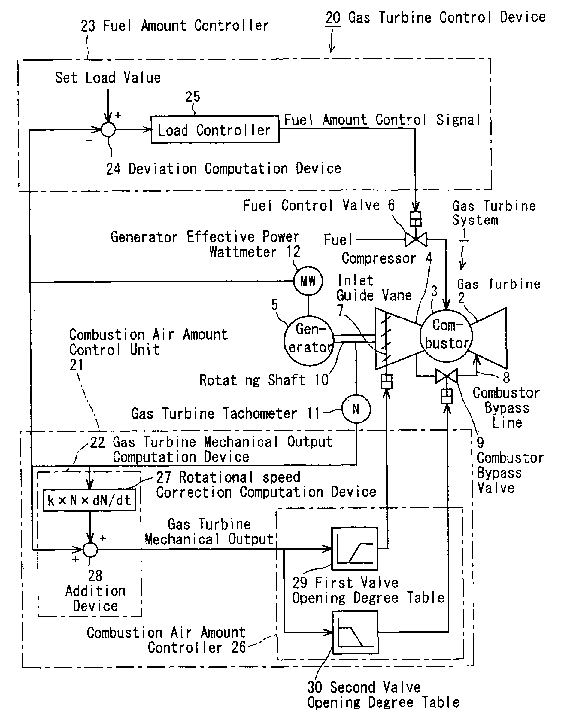
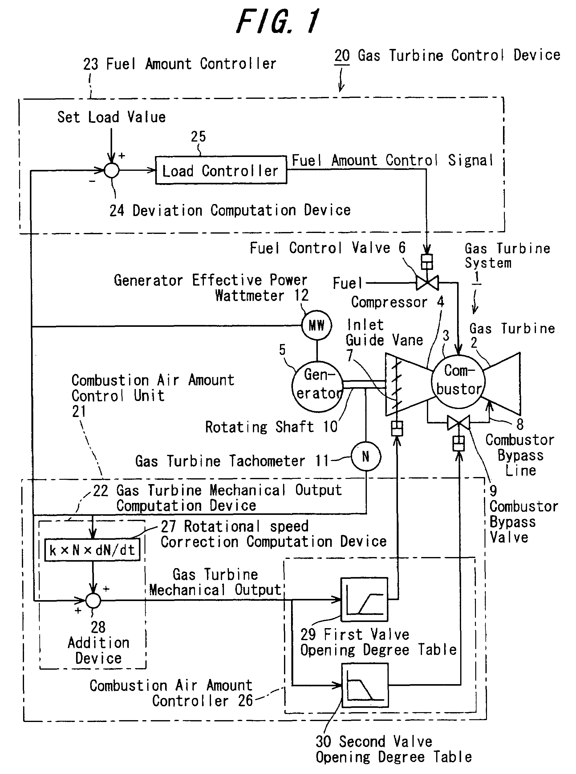
[0019]As shown in FIG. 1, a gas turbine system 1 has a gas turbine 2, a combustor 3, a compressor 4, a generator 5, and a gas turbine control device 20 for controlling these members.

[0020]The combustor 3 is placed upstream of the gas turbine 2, and is interposed between the gas turbine 2 and the compressor 4. A rotating shaft of the gas turbine 2, a rotating shaft of the compressor 4, and a rotating shaft 10 of the generator 5 are connected together so that the compressor 4 and the generator 5 may be rotationally driven by the gas turbine 2.

[0021]A fuel control valve 6 is connected to the combustor 3, and the adjustment of the opening degree of the fuel control valve 6 results in the adjustment of the amount of fuel supplied from fuel supply equipment (not shown) to the combustor 3. The compressor 4 is furnished with an inlet gui...


PUM


Abstract

A turbine mechanical output computation device computes a gas turbine mechanical output P from the following equationP=Pe+J×g×(2⁢π60)2×N×ⅆNⅆtwhere Pe represents a generator effective power measured by a generator effective power wattmeter, N represents the rotational speed of a gas turbine measured by a gas turbine tachometer, J represents the moment of inertia of the gas turbine, and g represents gravitational acceleration. A combustion air amount controller controls the amount of combustion air based on the gas turbine mechanical output P.

Description

CROSS REFERENCE TO RELATED APPLICATION[0001]The entire disclosure of Japanese Patent Application No. 2003-412870 filed on Dec. 11, 2003, including specification, claims, drawings and summary, is incorporated herein by reference in its entirety.BACKGROUND OF THE INVENTION[0002]1. Field of the Invention[0003]This invention relates to a turbine mechanical output computation device for computing the mechanical output of a turbine which rotationally drives a generator, and a gas turbine control device equipped with the turbine mechanical output computation device.[0004]2. Description of the Related Art[0005]In controlling a lowNOx combustor in a gas turbine, it is necessary to maintain the ratio between the amounts of fuel and combustion air, which are supplied to the combustor, i.e., fuel-air ratio, at a value in a predetermined range. For this purpose, the amount of fuel needs to be detected accurately and promptly.[0006]In the fuel-air ratio control of the gas turbine by a gas turbine...

Claims


Application Information

Patent Timeline
Patent Type & Authority Patents(United States)
IPC IPC(8): G06F19/00F01D17/00F01D15/10F01D17/02F02C7/042F02C7/057F02C9/28
CPCF01D15/10F02C9/28F05D2270/081Y02T50/677F05D2270/304F05D2270/061F05D2220/76Y02T50/60
Inventor FUJII, FUMINORI
Owner MITSUBISHI HITACHIPOWER SYST LTD
Why Eureka
Try Eureka