Magnetoresistance effect reproduction head
a technology of magnetoresistance effect and reproduction head, which is applied in the field of can solve the problems of fluctuations in the output of the magnetoresistance effect reproduction head, and achieve the effects of suppressing stable head output, and preventing fluctuations in the head outpu
- Summary
- Abstract
- Description
- Claims
- Application Information
AI Technical Summary
Benefits of technology
Problems solved by technology
Method used
Image
Examples
first embodiment
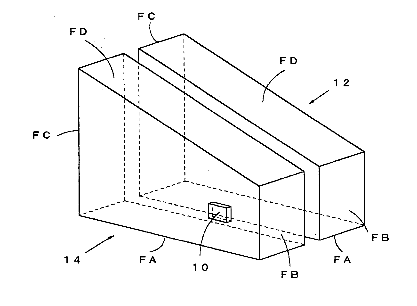
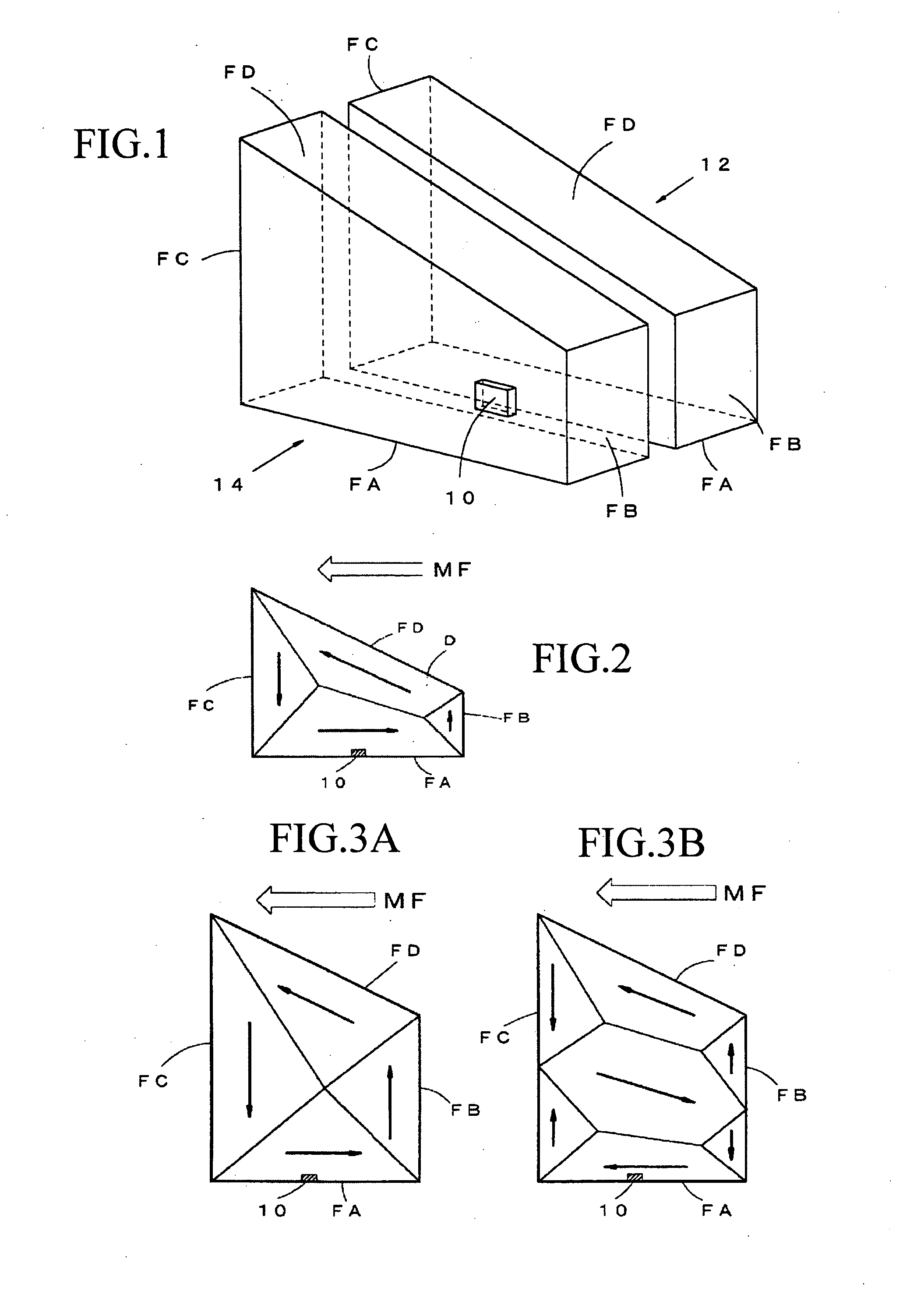
[0050]FIG. 1 is a perspective view showing the lower shield 12 and the upper shield 14 whose shapes are characteristic to the magnetoresistance effect reproduction head according to the present invention, as well as the magnetoresistance effect element 10. It should be noted that the structures of the laminated films composing the magnetoresistance effect element 10 and the structures of components composing the magnetoresistance effect reproduction head are fundamentally the same as magnetoresistance effect reproduction head described above. Accordingly, description thereof has been omitted below.
[0051] The most characteristic parts of the magnetoresistance effect reproduction head according to the present embodiment are the planar shapes of the lower shield 12 and the upper shield 14 that form a shield part of the magnetoresistance effect reproduction head. That is, while the lower shield 12 and the upper shield 14 are formed with rectangular or square planar shapes in the conven...
second embodiment
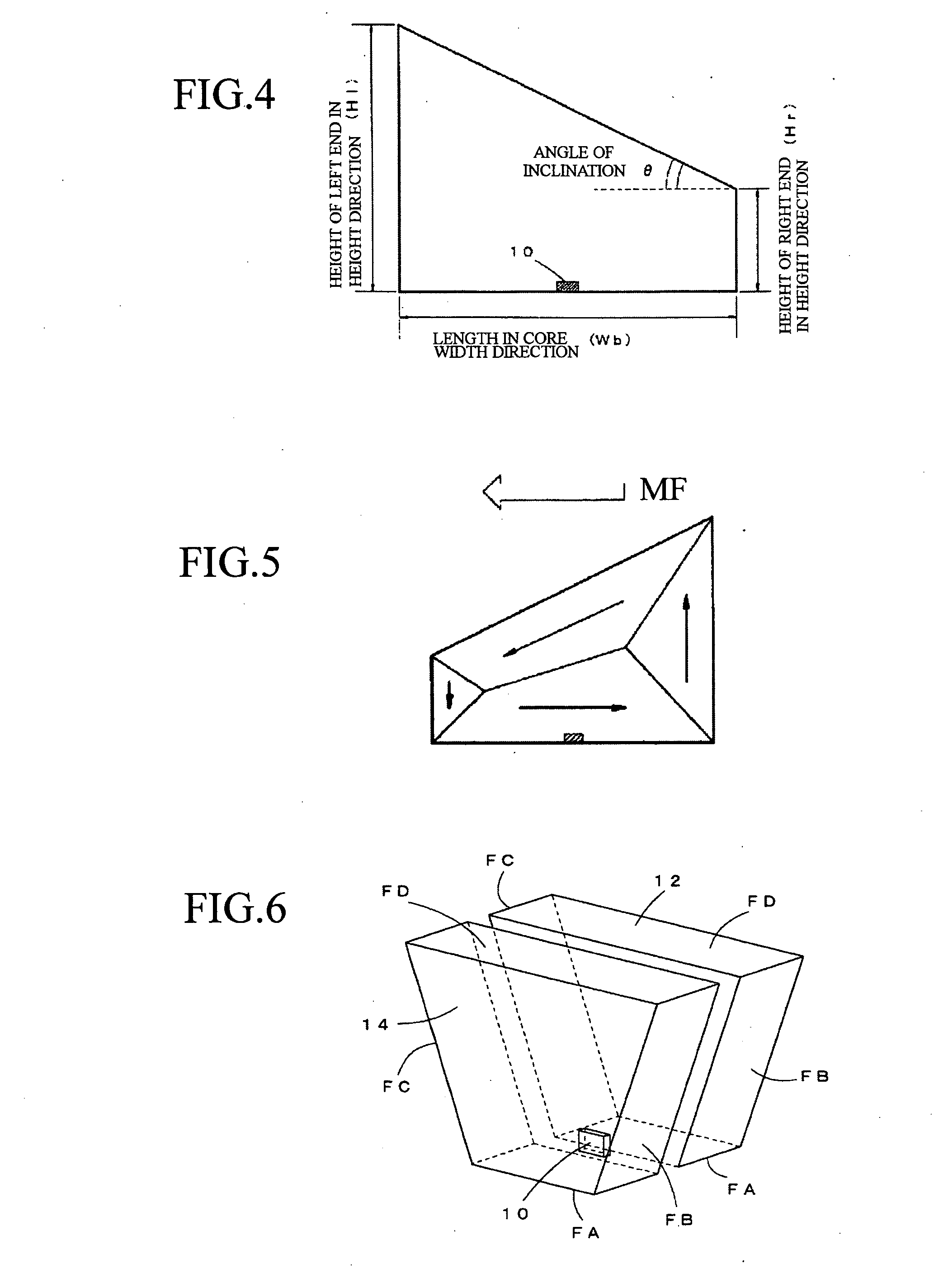
[0065]FIG. 6 shows a second embodiment of a magnetoresistance effect reproduction head according to the present invention. The present embodiment is characterized by the planar shapes of the lower shield 12 and the upper shield 14 that form the shield part being formed as isosceles trapezoids. The lengths of the lower end surfaces FA (the lengths in the core width direction) of the lower shield 12 and the upper shield 14 are set shorter than the upper end surfaces FD.
[0066]FIG. 7 shows the magnetic domain structure that appears in the lower shield 12 and the upper shield 14 whose planar shapes are isosceles trapezoids when the magnetizing magnetic force MF is first applied to the lower shield 12 and the upper shield 14 and then removed. As shown in FIG. 7, for the lower shield 12 and the upper shield 14 of the present embodiment, a clockwise magnetic domain structure appears in the lower shield 12 and the upper shield 14 due to the asymmetry of the lower shield 12 and the upper shi...
PUM
| Property | Measurement | Unit |
|---|---|---|
| angle of inclination | aaaaa | aaaaa |
| angle | aaaaa | aaaaa |
| height | aaaaa | aaaaa |
Abstract
Description
Claims
Application Information
 - R&D
- Intellectual Property
- Life Sciences
- Materials
- Tech Scout
- Unparalleled Data Quality
- Higher Quality Content
- 60% Fewer Hallucinations
Browse by: Latest US Patents, China's latest patents, Technical Efficacy Thesaurus, Application Domain, Technology Topic, Popular Technical Reports.
© 2025 PatSnap. All rights reserved.Legal|Privacy policy|Modern Slavery Act Transparency Statement|Sitemap|About US| Contact US: help@patsnap.com


