Method and system for determining downhole optical fiber orientation and/or location

a technology of optical fiber and orientation or location, which is applied in the direction of electrical/magnetic detection for well-logging, fluid removal, survey, etc., can solve the problems of increasing the material and production cost of the well, affecting the accuracy of the use of magnetometers to detect rods, and affecting the accuracy of the determination. , to achieve the effect of accurate determination

Active Publication Date: 2017-11-07
SILIXA
View PDF28 Cites 16 Cited by
  • Summary
  • Abstract
  • Description
  • Claims
  • Application Information

AI Technical Summary

Benefits of technology

[0037]Further embodiments of the present invention improve upon the arrangement described in WO2013 / 030555 by using higher frequency, ultrasonic transducers that are significantly more directional than conventional loudspeakers. Ultrasonic transducers, such as piezo or ferroelectric transducers, are known in the art that generate highly directional soundwaves with frequencies from 100 KHz up to many (50) MHz. As directionality of a sound transducer is proportional to the frequencies emitted therefrom, with higher frequencies typically being more directional, using an ultrasonic transducer results in a significantly more directional output than with conventional loudspeakers. Hence, if the fiber detects the highly directional soundwave, then it becomes possible to be more certain of the orientation of the object to which the transducer is affixed, knowing the relative arrangement between the transducer and the object.

Problems solved by technology

One issue with the use of perforating guns is to try and prevent the shaped charges from damaging any control or sensing cabling or other lines that may extend along the wellbore external of the casing.
As the perforating is performed as part of the well completion, by that point the fibers have typically already been cemented into the well bore, and hence repair can be very costly, or even impossible.
One problem with the above arrangement is one of cost, in that the metal rods are usually required to extend along a significant length of the well bore, hence increasing the material and production cost of the well.
In addition, the use of magnetometers to detect the rods is not particularly accurate, and particularly in some rock formations or in some regions where magnetic anomalies can occur that interfere with the operation of the magnetometers.
Moreover, the presence of the casing and other downhole equipment can interfere with the proper operation of the magnetometers, meaning that it is not reliably possible to rotationally orient the perforating gun within the casing to ensure that the sensor and control lines and / or other cabling will not be damaged by the use of the perforating gun.
In addition, the rods also from a potential leakage path up the outside of the casing.
Allowing further for echoes and other multi-path effects within the casing, and the reliability of such a system begins to deteriorate.
Basically, using conventional speakers as described in the prior art does not give a high enough directivity for the sound emitted to reliably determine the orientation of the perforating gun.

Method used


Image

  • Method and system for determining downhole optical fiber orientation and/or location
  • Method and system for determining downhole optical fiber orientation and/or location
  • Method and system for determining downhole optical fiber orientation and/or location

Examples


first embodiment

[0064]the present invention will be described with respect to FIGS. 4a and 4b.

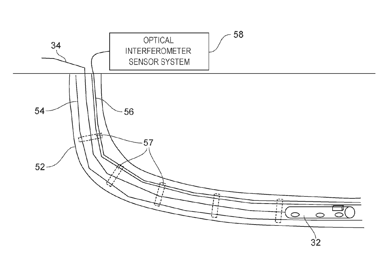
[0065]FIG. 4a illustrates that the transducer 36 may be an electrical or mechanical tapper device 36a, that is arranged to rotate about an axis and tap at discrete points on the inner surface of casing 54 as it rotates through 360 degrees. In this embodiment the optical interferometric sensing system 58 operates as a distributed acoustic sensor (DAS), which listens to the acoustic energy from the taps and determines its amplitude and / or power. A plot of the measured amplitude and / or power with respect to angular position of the tapper as it rotates within the casing is made, as shown in FIG. 4b. With reference to the orientational axes shown in FIG. 4a, a minima in the measured amplitude or power plot is expected when the tapper is aligned with the x-axis of FIG. 4a i.e. when it is substantially orthogonal to the position of the optic fiber 56, whilst a primary maxima in amplitude or power is obtained whe...

second embodiment

[0067]the invention will now be described with respect to FIGS. 6a and 6b. In this embodiment the optical interferometric sensing system 58 operates as a distributed temperature sensor (DTS) that acts to determine the temperature of the casing 54, inter alia. The transducer 36 is a heated probe, similar to the tip of a soldering iron, that is rotationally mounted on the perforating gun, or alternatively on another down-hole device that acts as a carriage for the probe. In some embodiments this may be preferable, so that the heated tip is not maintained near the explosives that are contained within the perforating gun. The heated probe is in contact with the inner surface of the casing 54, and acts to heat the casing wall in the immediate vicinity of the probe. The degree of local heating provided by the probe need not be large, and may even be less than 1K, for the reason that modern DTS systems have very high temperature resolutions, as high as 0.01K.

[0068]The local heating of the ...

third embodiment

[0072]the invention will now be described with respect to FIGS. 8a and 8b. In this embodiment the optical interferometric sensing system 58 operates as a distributed temperature sensor (DTS) that acts to determine the temperature of the casing 54, inter alia. The transducer 36 is a probe with a heated tip 36c and a cooled tip 36d, wherein the probe is heated on one side and cooled on the opposite side, that is rotationally mounted on a perforating gun, or alternatively on another down-hole device that acts as a carriage for the probe. In some embodiments this may be preferable, so that the heated part of the probe is not maintained near the explosives that are contained within the perforating gun. The probe is in contact with the inner surface of the casing 54, and acts to heat or cool the casing wall in the immediate vicinity of the probe. The degree of local heating provided by the probe need not be large, and may even be less than 1K, for the reason that modern DTS systems have v...


PUM

PropertyMeasurementUnit
lengthaaaaaaaaaa
frequenciesaaaaaaaaaa

Abstract

A probe is provided that contacts the inner surface of the casing or other production tubing and imparts energy to the surface at the contact point, for example as heat energy or mechanical energy. Energy is imparted around the circumference of the casing, and a fiber optic distributed sensor located on the outer surface of the casing is used to measure and record the energy that it receives whilst the probe is moved to impart energy around the circumference. A record of energy versus position of the probe around the circumference can be obtained, from which maxima in the detected energy measurements can then be found. The position around the circumference which gave the maximum measurement should be the position at which the optical fiber of the fiber optic distributed sensor is located. In addition, an ultrasonic arrangement is also described, that relies on ultrasonic sound to provide detection.

Description

CROSS-REFERENCE TO RELATED APPLICATIONS[0001]This application claims priority under 35 U.S.C. §371 to Patent Cooperation Treaty Application No. PCT / GB2015 / 050242, filed Jan. 30, 2015, which claims priority to GB Application No. 1401671.1, filed Jan. 31, 2014, to GB Application No. 1408760.5, filed May 16, 2014, and to GB Application No. 1419263.7, filed Oct. 29, 2014, the entire contents of which are incorporated herein by reference.TECHNICAL FIELD[0002]The present invention provides a method and system for determining the orientation or location of optical fiber deployed downhole, and particularly optical fiber used for distributed acoustic or temperature sensing. Particular embodiments provide a method and system that ensure that the perforation gun will not damage any optical fibres installed in the well.BACKGROUND TO THE INVENTION AND PRIOR ART[0003]To detect an acoustic signal downhole, distributed acoustic sensing (DAS) is commonly and effectively used. This method employs fib...

Claims


Application Information

Patent Timeline
Patent Type & Authority Patents(United States)
IPC IPC(8): G01N21/00G01V11/00G01N21/64G01N21/68
CPCG01V11/005G01N21/68G01N21/64E21B43/116E21B43/119E21B47/024E21B47/09E21B47/14E21B47/0224E21B47/092E21B47/095G01V1/44G01V3/30G01V9/00
Inventor FARHADIROUSHAN, MAHMOUDPARKER, TOM
Owner SILIXA
Why Eureka
Try Eureka