Fuel injector nozzle seal

a technology of nozzle seals and fuel injectors, which is applied in the direction of engine seals, fuel injection apparatus, charge feed systems, etc., can solve the problems of high demands on the accuracy of component fit, complicated installation, and high cost, and achieve the effect of smooth surfa

Inactive Publication Date: 2007-08-28
ROBERT BOSCH GMBH +1
View PDF13 Cites 14 Cited by
  • Summary
  • Abstract
  • Description
  • Claims
  • Application Information

AI Technical Summary

Benefits of technology

[0006]In contrast, the fuel injector according to the present invention has the advantage that a seal is situated between the cylinder head and the nozzle body, the seal extending over the entire axial length and having a suitable structure, thereby providing not only a reliable sealing effect but effective heat dissipation away from the nozzle body as well.
[0008]In an advantageous manner the seal may also be made up of a plurality of layers, which gives it higher stability and makes it less likely to be damaged during the installation.
[0010]The seal may be produced from a metallic material having an amorphous structure, so that a smooth surface is able to be achieved.

Problems solved by technology

Disadvantages of the fuel injector described in the European patent document EP 0 828 075 are the high demands regarding the accuracy of fit of the components and the complicated installation, which is involved and thus cost-intensive.
Particularly disadvantageous in the fuel injector described in published German patent document DE 101 09 407 is the air gap between the fuel injector and the cylinder head, which allows only limited heat transfer.
This is disadvantageous in reducing deposits on the valve tip since the temperature in the region of the spray-discharge orifices must be as low as possible so as to avoid deposits.

Method used


Image

  • Fuel injector nozzle seal
  • Fuel injector nozzle seal
  • Fuel injector nozzle seal

Examples


Embodiment Construction

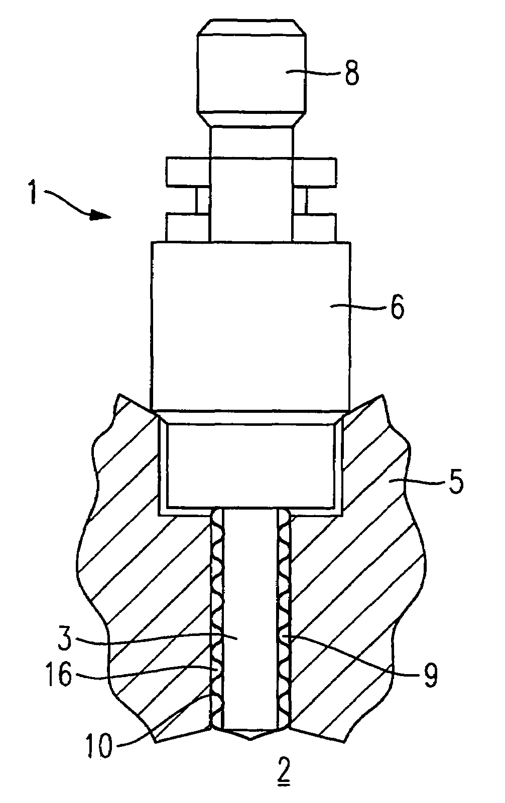
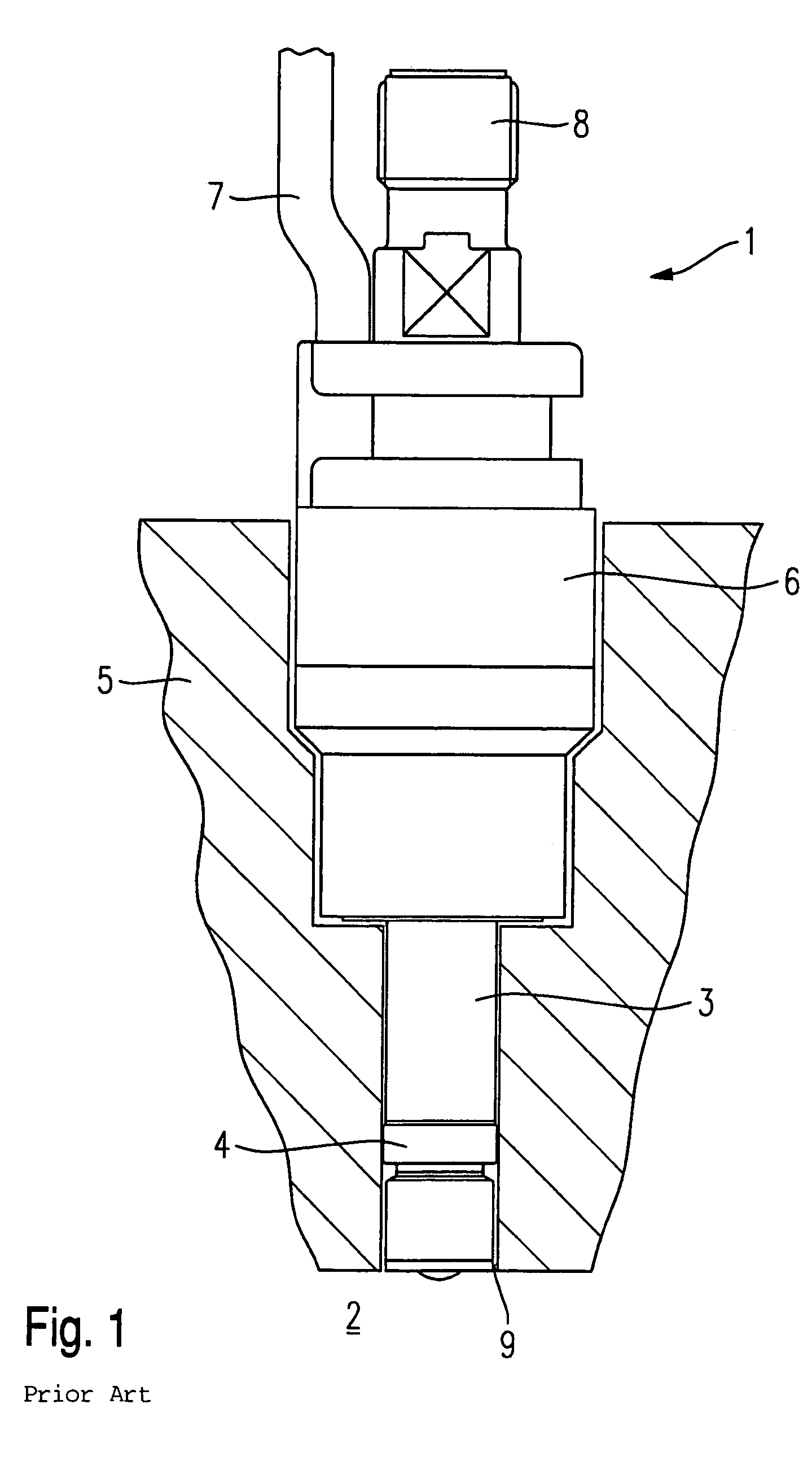
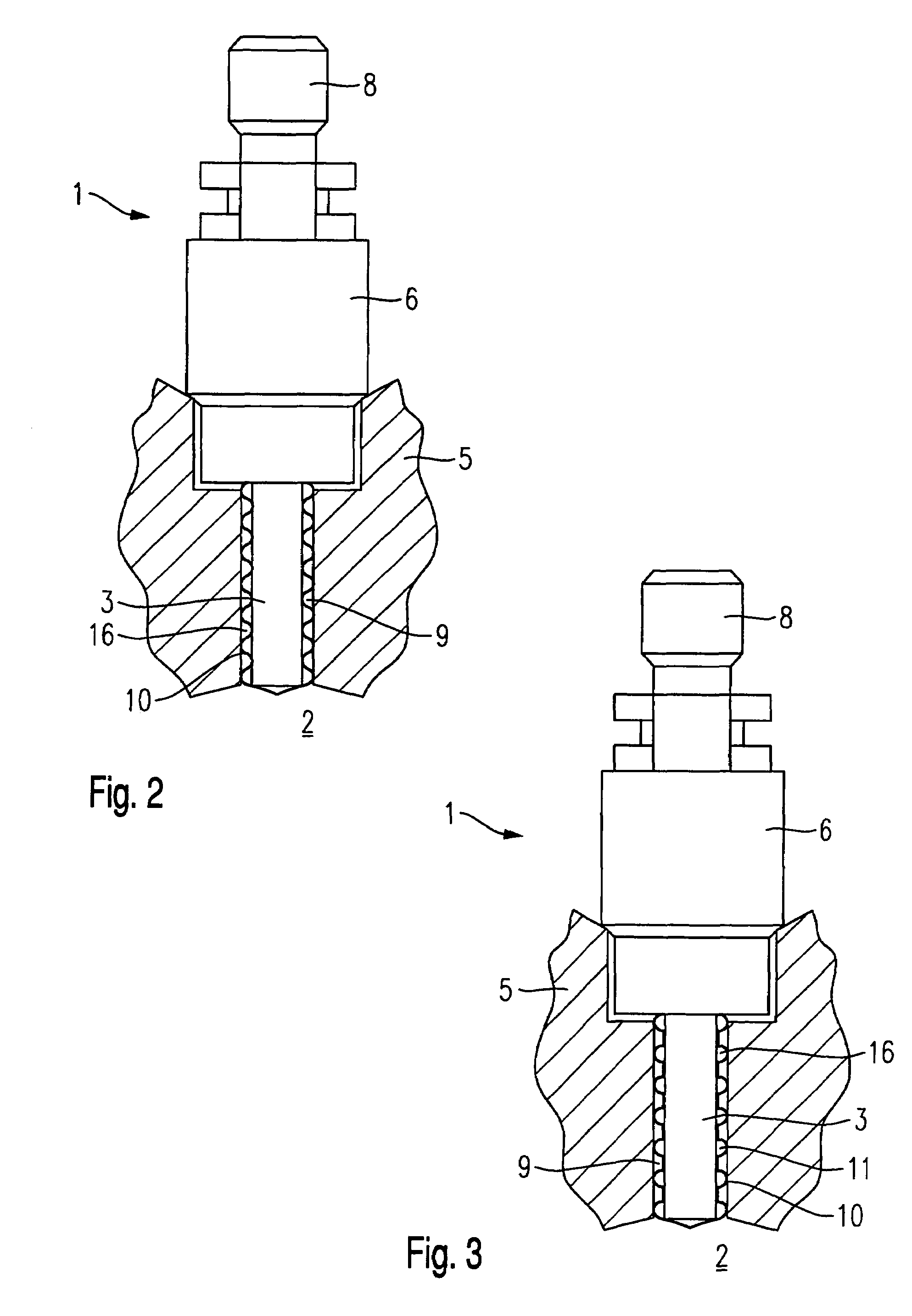
[0018]Before example embodiments of a fuel injector 1 according to the present invention are described in greater detail in connection with FIGS. 2 through 7, for a better understanding of the present invention, a conventional fuel injector 1 will be briefly explained in terms of its essential components on the basis of FIG. 1.

[0019]Fuel injector 1 is configured for fuel-injection systems of mixture-compressing internal combustion engines with externally supplied ignition. Fuel injector 1 is suited, e.g., for the direct injection of fuel into a combustion chamber 2 of an internal combustion engine.

[0020]Fuel injector 1 includes a nozzle body 3, which is sealed from a cylinder head 5 of the internal combustion engine by a sealing ring 4. Sealing ring 4 is made of, for instance, an elastomeric material such as a Teflon-coated material and provides the sealing effect in cylinder head 5 as a result of a slightly larger diameter compared to nozzle body 3.

[0021]Furthermore, fuel injector ...


PUM


Abstract

A fuel injector for the direct injection of fuel into the combustion chamber of a mixture-compressing internal combustion engine having external ignition includes a valve housing formed by a nozzle body, and a seal which seals the fuel injector from a cylinder head of the internal combustion engine. The seal has a sleeve-type design with a structured cross section and extends across the axial length of the nozzle body.

Description

FIELD OF THE INVENTION[0001]The present invention relates to a fuel injector for direct injection of fuel, which fuel injector is provided with a seal.BACKGROUND INFORMATION[0002]Published European patent document EP 0 828 075 describes a fuel injector for the direct injection of fuel into the combustion chamber of an internal combustion engine, which has a device for adjusting the temperature in the region of the valve tip so as to reduce deposits in this area. The device is embodied in the form of a coating made of a thermally conductive material on the valve tip.[0003]Disadvantages of the fuel injector described in the European patent document EP 0 828 075 are the high demands regarding the accuracy of fit of the components and the complicated installation, which is involved and thus cost-intensive.[0004]Furthermore, a fuel injector for the direct injection of fuel into the combustion chamber of a mixture-compressing internal combustion engine having external ignition is describe...

Claims


Application Information

Patent Timeline
Patent Type & Authority Patents(United States)
IPC IPC(8): F02M61/14F02M37/04F02M53/04
CPCF02M53/04F02M61/14
Inventor HOENIG, GUENTERWUERFEL, GERNOTNOWAK, DETLEFMLEJNEK, ANDREASROESSLER, KLAUS
Owner ROBERT BOSCH GMBH
Why Eureka
Try Eureka