Control of induction system hydrocarbon emissions

a technology of induction system and hydrocarbon emission control, which is applied in the direction of liquid fuel feeders, machines/engines, combustion air/fuel air treatment, etc., can solve the problems of adding cost and complexity to the manufacture of vehicles, and achieve the effect of reducing or preventing hydrocarbon emissions of residual hydrocarbons

Active Publication Date: 2007-08-28
GM GLOBAL TECH OPERATIONS LLC
View PDF9 Cites 3 Cited by
  • Summary
  • Abstract
  • Description
  • Claims
  • Application Information

AI Technical Summary

Benefits of technology

[0004]In an embodiment of the invention, a method for reducing or preventing hydrocarbon emissions of residual hydrocarbons in an air induction system when an automotive vehicle is not in operation directs residual hydrocarbon (present as vapor, liquid, or both) in the vehicle air induction system into the engine oil crankcase. The crankcase retains the hydrocarbon, and the engine oil may absorb such low amounts of hydrocarbon without detriment.
[0005]In an embodiment of the invention, an apparatus for reducing or eliminating emissions of residual hydrocarbon present in an automotive vehicle air induction system when the vehicle is not in operation includes a vent or other opening located in an underside portion of the air induction system, an orifice or other opening in an engine oil crankcase, and a hollow connector between the vent and the orifice. The vent and orifice are opened when the vehicle is not in operation to allow any hydrocarbon in the air induction system to be introduced into the crankcase through the connector.
[0007]The invention further provides a method for reducing or preventing hydrocarbon emissions of residual hydrocarbons in a portion of an air intake system for an engine having a crankcase containing engine oil, in which, when the engine is not operating, the portion of the air induction system is vented into the crankcase.

Problems solved by technology

Hydrocarbon traps containing an adsorbent such as activated carbon may be added to the air intake to absorb such emissions, which may then be desorbed by engine intake air when the engine is operating, but would add cost and complexity to manufacture of the vehicle.

Method used


Image

  • Control of induction system hydrocarbon emissions
  • Control of induction system hydrocarbon emissions
  • Control of induction system hydrocarbon emissions

Examples


Embodiment Construction

[0014]The following description of the preferred embodiment(s) is merely exemplary in nature and is in no way intended to limit the invention, its application, or uses.

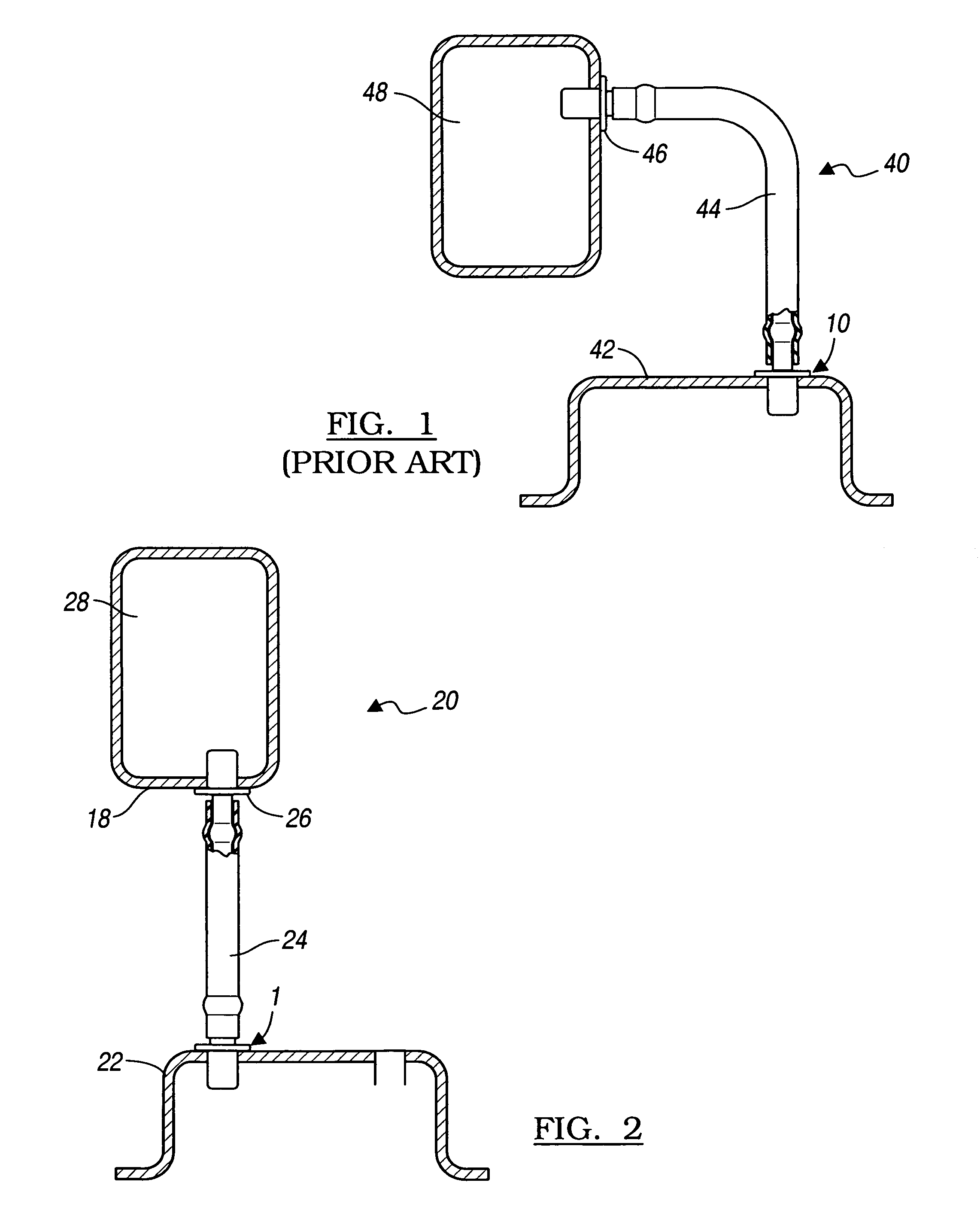
[0015]Positive crankcase ventilation (PCV) systems reduce emission of contaminants by recirculating blowby gases and crankcase vapors into the engine cylinders for burning. During operation of an automotive vehicle with an internal combustion engine, crankcase vapors are drawn through a liquid separator and into the air intake manifold (a part of the air induction system) where they will be drawn into the cylinders by intake manifold vacuum. FIG. 1 schematically illustrates a prior art design of a positive crankcase ventilation orifice. In FIG. 1, PCV orifice 10 in engine PCV system 40 is mounted in an oil separation portion 42 of a cylinder head cam cover of the crankcase. The orifice 10 connects directly with a PCV hose 44 that leads to a fitting 46 on the engine intake manifold 48 for recirculating blowby and crank...


PUM


Abstract

A method and apparatus for reducing or preventing hydrocarbon emissions from an air induction system of an automotive vehicle directs hydrocarbon from induction system into the crankcase when the vehicle is not in operation.

Description

FIELD OF THE INVENTION[0001]The present invention relates generally to systems and methods for controlling hydrocarbon emissions in automotive vehicles.BACKGROUND OF THE INVENTION[0002]The automotive industry has actively sought improved emissions reduction, including reduction in emissions due to gasoline evaporation. Gasoline includes a mixture of hydrocarbons ranging from higher volatility butanes (C4) to lower volatility C8 to C10 hydrocarbons. When vapor pressure increases in the fuel tank due to conditions such as higher ambient temperature or displacement of vapor during filling of the tank, fuel vapor may flow through openings in the fuel tank and escape into the atmosphere. To prevent fuel vapor loss into the atmosphere, the fuel tank is vented into a canister called an “evap canister” that contains an adsorbent material such as activated carbon granules. As the fuel vapor enters an inlet of the canister, the fuel vapor diffuses into the carbon granules and is temporarily a...

Claims


Application Information

Patent Timeline
Patent Type & Authority Patents(United States)
IPC IPC(8): F02M25/06
CPCF01M13/00F02M25/06F02M33/025F02M35/04Y02T10/121Y02T10/12F02B25/06F02M25/08
Inventor REDDY, SAM R.
Owner GM GLOBAL TECH OPERATIONS LLC
Why Eureka
Try Eureka