Device for actuating locks on doors or hatches of vehicles

a technology for actuating devices and doors, which is applied in the direction of locking applications, mechanical devices, and fastening means, etc. it can solve the problems of large space, cumbersomeness, and high cost of snow load devices, and achieve the effect of saving space and small in siz

Inactive Publication Date: 2007-08-28
HUF HULSBECK & FURST GMBH & CO KG
View PDF9 Cites 12 Cited by
  • Summary
  • Abstract
  • Description
  • Claims
  • Application Information

AI Technical Summary

Benefits of technology

[0010]It is an object of the present invention to develop a reliable device of the aforementioned kind that is small in size and saves space and is inexpensive.
[0013]This is sufficient for configuring a snow load device. According to the invention, the snow load device requires no additional components. It is sufficient to have available the elements that are present within a lock in any case, i.e., the catch, the catch spring, and the rotary latch. Accordingly, the special components of the known snow load devices as disclosed in the art are no longer needed. Not only is it no longer required to produce and mount these special components, but valuable space within the lock is made available. The invention is of a very simple configuration so that the device will cause no disruptions or failure. The device according to the present invention functions very reliably.

Problems solved by technology

The weight of the snow presses the rear hatch so tightly into the lock member that the return force of the seal and / or the spring load is not sufficient for transferring the rotary latch into the open position.
It is then necessary to actuate the catch again; this is perceived as cumbersome.
The known snow load devices are expensive and require a large space.
These securing means take up a large space within the lock.

Method used


Image

  • Device for actuating locks on doors or hatches of vehicles
  • Device for actuating locks on doors or hatches of vehicles
  • Device for actuating locks on doors or hatches of vehicles

Examples


first embodiment

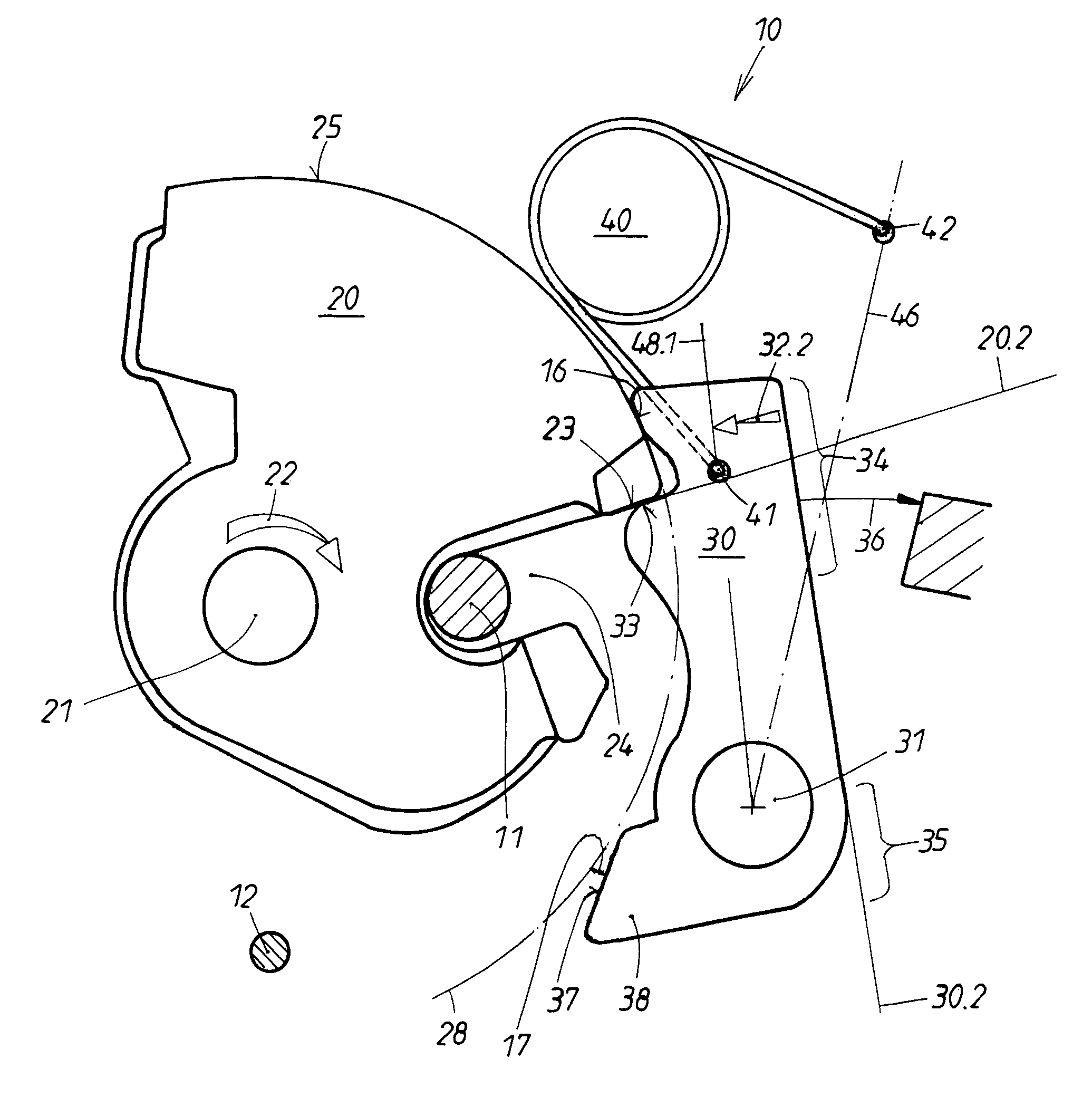
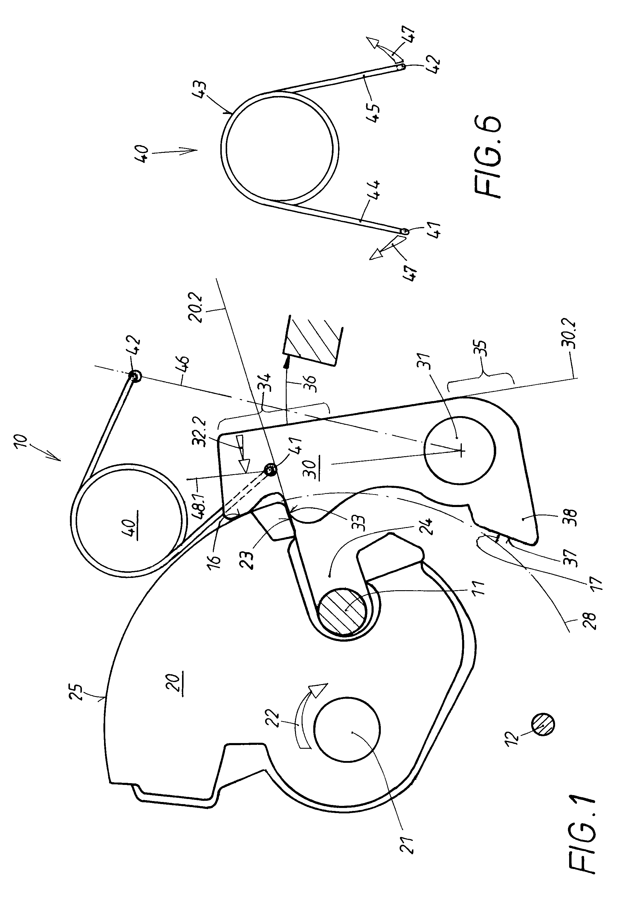
[0026]When supposing that each lock of the inventive kind comprises a rotary latch 20 and a catch 30, a snow load device 10 is comprised according to the invention only of the special configuration of the catch spring 40, i.e., it is a so-called over-center helper spring. As already mentioned, in the first embodiment this over-center helper spring is a tangentially loaded helical spring (“leg spring”). Since each lock requires a single catch spring 40, it can be said that the snow load device according to the invention is characterized by the special feature of requiring no additional lock parts.

[0027]The rotary latch 20 is supported so as to rotate on a stationary rotary pin 21 in the lock housing (not illustrated in detail) and is exposed to the action of a spring load that is illustrated by the arrow 22. This spring load 22 has the effect of transferring the rotary latch 20 into the open position illustrated in FIG. 5 by the auxiliary line 20.1. This open position 20.1 is determi...

third embodiment

[0045]The latter holds true also for the third embodiment according to FIG. 8. The over-center helper spring is embodied as a tension spring 60 whose ends 61, 62 engage the device as illustrated in FIG. 8. The first end 61 is arranged to be movable with the catch 30 and is therefore referred to as the moving end. The second spring end 62 is stationary and is located on the dead center line 46 that has been mentioned above. The end 62 is therefore the fixed end of the tension spring 60.


PUM


Abstract

A device for actuating locks on a vehicle door has a rotary latch spring-loaded into an open position. When the door is closed, the rotary latch receives a lock member of the lock and is rotated into a defined locked position. The rotary latch has a detent into which a pivotable catch drops in a blocking position for securing the locked position of the rotary latch. A catch spring forces the catch into the blocking position. An actuation is provided for lifting the catch from the blocking position into a release position for releasing the rotary latch. The catch spring is an over-center helper spring that reverses a direction of action of the spring force. The catch spring acts as a snow load device that holds the catch in the release position until the rotary latch has reached the open position.

Description

BACKGROUND OF THE INVENTION[0001]1. Field of the Invention[0002]The invention relates to a device for actuating locks on hatches or doors of vehicles, comprising a rotary latch in the lock that is spring-loaded into its open position, wherein the rotary latch, when the hatch or the door is closed, receives a lock member provided stationarily on the vehicle and is rotated into at least one defined position (locked position). The device further comprises a detent on the rotary latch into which, upon rotation of the rotary latch, a catch, pivotably and stationarily supported in the lock, drops so as to define a blocking position of the catch and to secure the locked position of the rotary latch. The device further comprises a catch spring that forces the catch into the blocking position. An actuation that is operated manually or by means of a motor is provided for lifting the catch from its blocking position into a release position in which the rotary latch is released. A snow load dev...

Claims


Application Information

Patent Timeline
Patent Type & Authority Patents(United States)
IPC IPC(8): E05C3/06
CPCE05B85/26E05B81/15E05B2015/0493Y10T292/1047Y10T292/1082
Inventor KIEHL, ERIK
Owner HUF HULSBECK & FURST GMBH & CO KG
Why Eureka
Try Eureka