Illuminated ball and mating element for forming such ball

a technology of mating element and ball, which is applied in the field of illuminated balls, can solve the problems of changing the weight distribution and performance of the ball, limiting the use of balls for recreation activities, and many problems with the manufacturing and/or use of many previously developed illuminated balls, etc., and achieves the effect of less denseness

Inactive Publication Date: 2007-08-28
HABITZ GERETT
View PDF23 Cites 58 Cited by
  • Summary
  • Abstract
  • Description
  • Claims
  • Application Information

AI Technical Summary

Benefits of technology

[0012]The ball may further comprise a light source positioned within the channel. The light source may be selected from chemiluminescent light sources, phosphorescent light sources, and electrical light sources. The light source and the channel may be substantially cylindrical in shape, with the light source having an outer diameter approximately the same as the inner diameter of the channel, such that the light source is retained within the channel by friction. There may also be a means for retaining the light source inside the channel through the ball, such as caps that seal the ends of the channel. The two mating elements may be engaged together with an engagement means, such as tape, glue, hook and loop fasteners, ratchet mechanisms, tongue and groove mechanisms, or combinations thereof. The ball may be less dense than water.

Problems solved by technology

In general, recreational activities using balls are limited to daylight unless the playing area is artificially illuminated or the ball is illuminated.
However, several problems are encountered with the manufacturing and / or use of many of the previously developed illuminated balls.
If the light source can move around within the interior of the ball, it changes the weight distribution and performance of the ball while in use, and it may also damage the light source.
If the light source is electrical and the ball is used for activities where it is subjected to impacts, such as being thrown into the air and landing on the ground, being caught between a dog's jaws, being kicked, or being hit with a bat, mallet, or other hard object, there is a high risk that some part of the electrical system will fail.

Method used


Image

  • Illuminated ball and mating element for forming such ball
  • Illuminated ball and mating element for forming such ball
  • Illuminated ball and mating element for forming such ball

Examples


Embodiment Construction

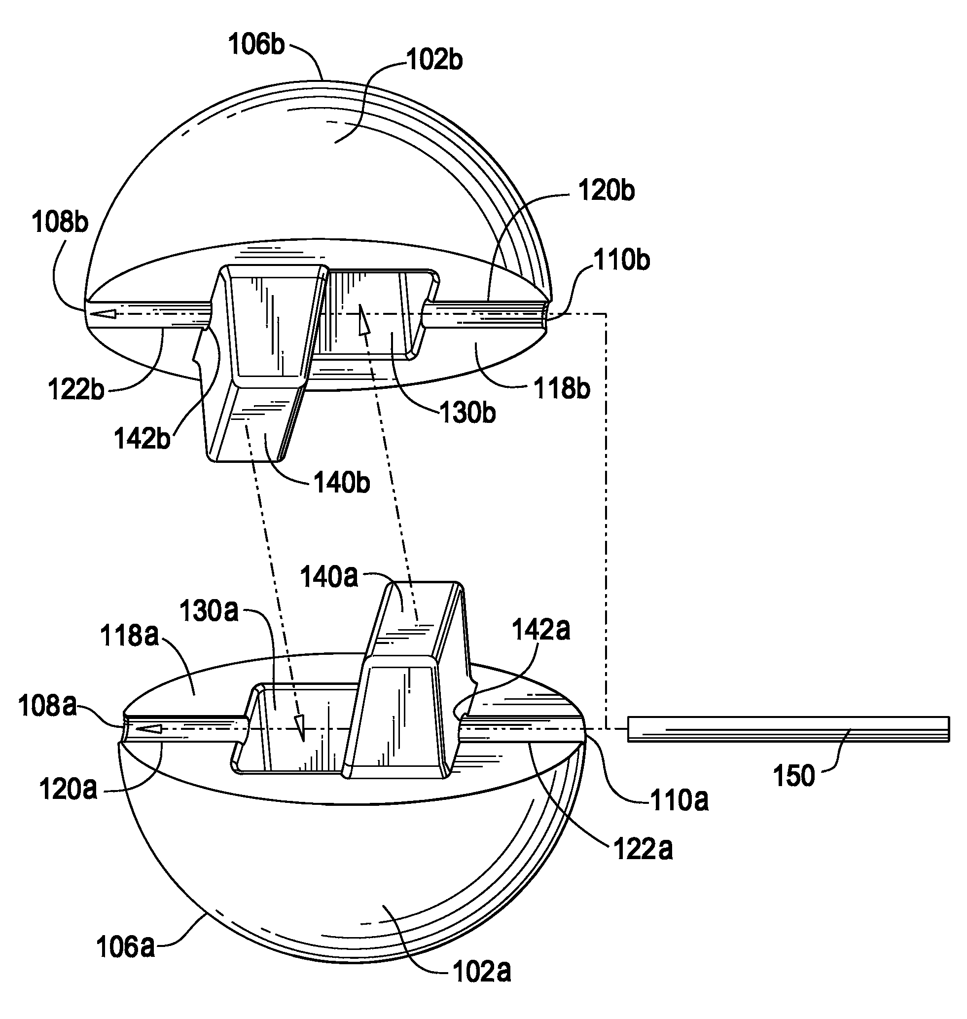
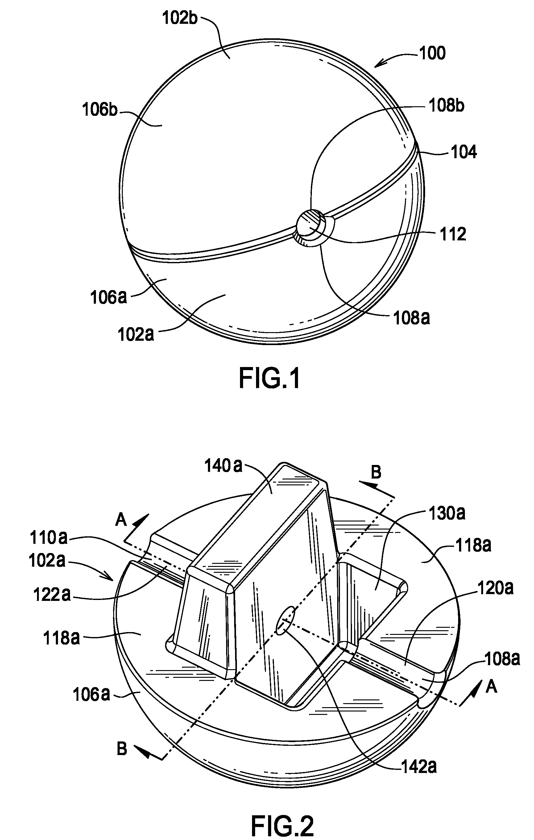
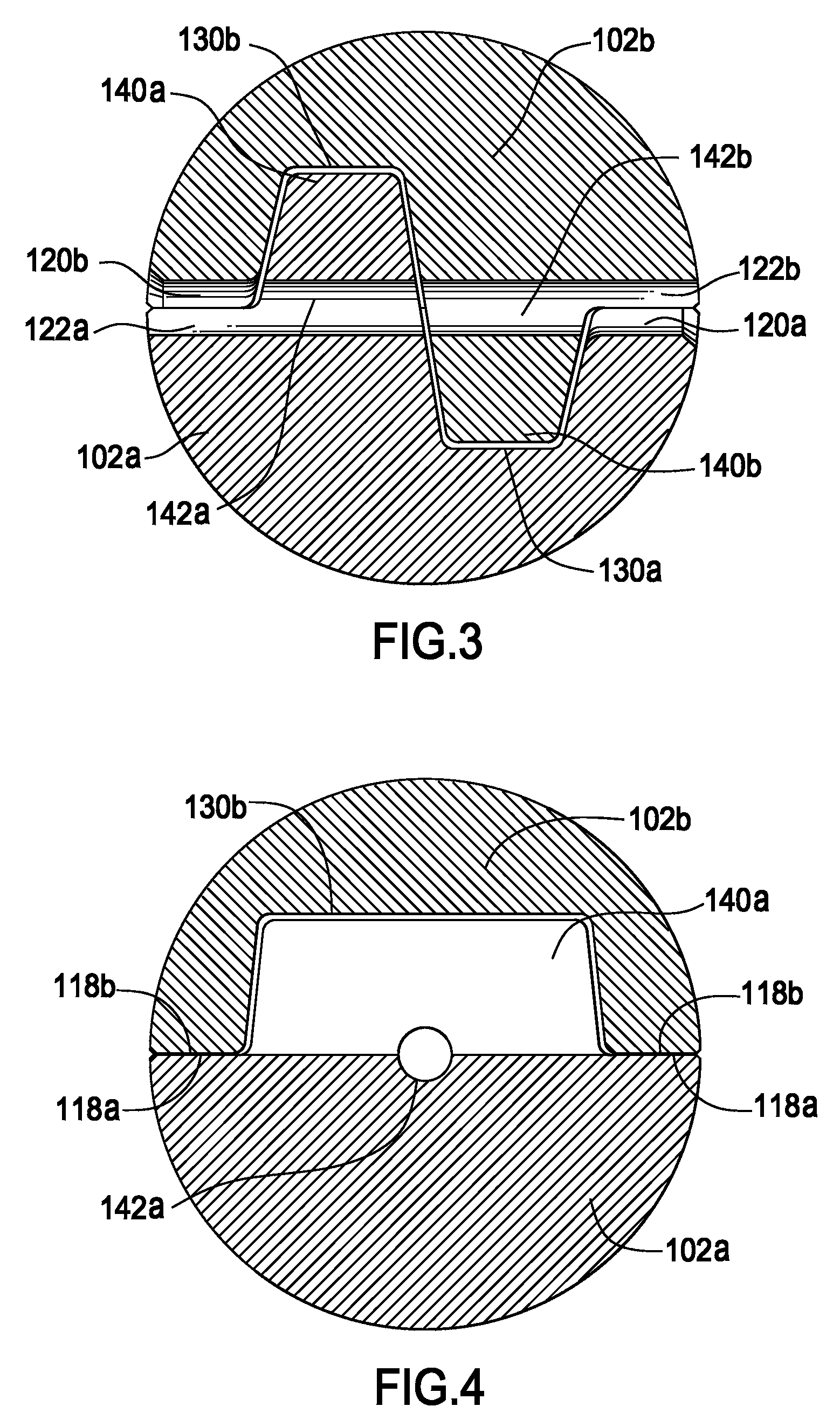
[0020]One embodiment of the present invention comprises a ball 100, as shown in FIGS. 1-5. The ball 100 comprises two identical mating elements 102a and 102b that meet at a seam 104 that runs around the circumference of the ball 100. Mating elements 102a and 102b each have a substantially hemispherical exterior surface 106a and 106b, respectively, with openings 108a and 108b, 110a, and 110b, respectively, on opposing sides of seam 104. Each opening 108a, 108b, 110a, and 110b has a substantially semicircular profile at its intersection with the respective exterior surface 106a or 106b. The mating elements 102a and 102b are mated with each other such that the openings 108a and 108b are aligned with each other to form openings 112 and 114 in the exterior of the ball, centered on the seam 104 between the mating elements 102a and 102b. The openings 112 and 114 are aligned with each other along an axis passing through the ball, and they form the ends of a channel passing through the inter...


PUM


Abstract

An illuminated ball formed by two substantially identical mating elements. Each mating element has an exterior surface bounded by an edge, an annular surface joined to said exterior surface at the edge, two opposed radial recesses formed in the annular surface, a well abutting a portion of the annular surface and one of the recesses, and an alignment guide abutting a portion of the annular surface and the other of the recesses. The alignment guide extends away from the exterior surface and includes a hole therethrough in alignment with the recesses. The mating element is matable with a second, substantially identical mating element by the well of each mating element receiving the alignment guide of the other element. The channel formed by the cooperation of the recesses and holes of both mating elements is sized to contain a light source.

Description

FIELD OF THE INVENTION[0001]The present invention relates generally to an illuminated toy and more specifically to an illuminated ball for use by humans and pets.BACKGROUND OF THE INVENTION[0002]Balls have been used for recreational activities for centuries. All sorts of ball games are played by humans, with formal or informal rules and balls that are spherical or toroidal in shape. Examples of ball games include catch, baseball, softball, football, basketball, soccer, volleyball, rugby, croquet, tennis, table tennis, etc. Balls have also been used for recreational activities with and by pets. One such game is fetch, played with dogs. Also, balls can be rolled or tossed to other animals, with the animal stopping or catching the ball. These games use balls of all sizes, sometimes as small as marbles and sometimes as large as beach balls. In general, recreational activities using balls are limited to daylight unless the playing area is artificially illuminated or the ball is illuminat...

Claims


Application Information

Patent Timeline
Patent Type & Authority Patents(United States)
IPC IPC(8): A63B43/06A63H33/22
CPCA63B43/06A63H33/22
Inventor HABITZ, GERETT
Owner HABITZ GERETT
Why Eureka
Try Eureka