Compact radial counterflow recuperator

a radial counterflow and recuperator technology, applied in the field of compact, high-temperature gastogas heat exchangers, can solve the problems of leakage of high-temperature heat exchangers, and achieve the effects of reducing manufacturing costs, reducing manufacturing costs, and reducing the number of parts

Active Publication Date: 2013-11-05
UNITED STATES OF AMERICA
View PDF17 Cites 12 Cited by
  • Summary
  • Abstract
  • Description
  • Claims
  • Application Information

AI Technical Summary

Benefits of technology

[0009]The invention satisfies the above-described and other needs by providing for a higher-effectiveness compact heat exchanger that can be manufactured inexpensively from materials that are cheaper, less dense, lighter, and can withstand higher temperatures than metal alloys. Additionally, the heat exchanger can include features that reduce thermal stresses, a major cause of leaks in high-temperature heat exchangers.
[0011]For another aspect of the invention, an engine assembly can incorporate the heat exchanger described above. Specifically, the engine assembly includes a compressor that can be configured for compressing inlet air. Secondly, the heat exchanger can be configured to preheat the compressed inlet air. The preheated compressed inlet air can then enter a combustor, located in the center of the heat exchanger, which can be configured to receive the preheated compressed air and an injected fuel from one or more fuel injectors. The fuel injectors can be located downstream from the heat exchanger. The combustor can allow the combustion of the injected fuel to occur, and the products of combustion can be used to perform useful work by expansion through a turbine, or other expansion means. The exhaust can then flow back through the heat exchanger, which can use the waste heat from the turbine exhaust to provide the energy needed to preheat the incoming compressed inlet air.
[0012]For another aspect of the invention, a heat-recirculating combustor assembly can incorporate the heat exchanger described above. A source of air can be provided to a mixing volume, which can be configured to thoroughly mix the compressed inlet air with fuel injected by one or more fuel injectors, upstream from the heat exchanger. The heat exchanger described above can then be configured to preheat the fuel and air mixture and send it to a combustor. The combustor, located in the center of the heat exchanger, can receive the preheated the fuel and air mixture downstream of the heat exchanger and allow combustion to occur. The products of combustion can be utilized for a useful purpose, then collected and supplied back to the heat exchanger, which uses the waste heat from the used combustion products to provide the energy needed to preheat the incoming fuel and air mixture.

Problems solved by technology

Additionally, the heat exchanger can include features that reduce thermal stresses, a major cause of leaks in high-temperature heat exchangers.

Method used


Image

  • Compact radial counterflow recuperator
  • Compact radial counterflow recuperator
  • Compact radial counterflow recuperator

Examples


Embodiment Construction

[0020]Referring now to the drawings, in which like numerals represent like elements, aspects of the exemplary embodiments will be described in connection with the drawing set.

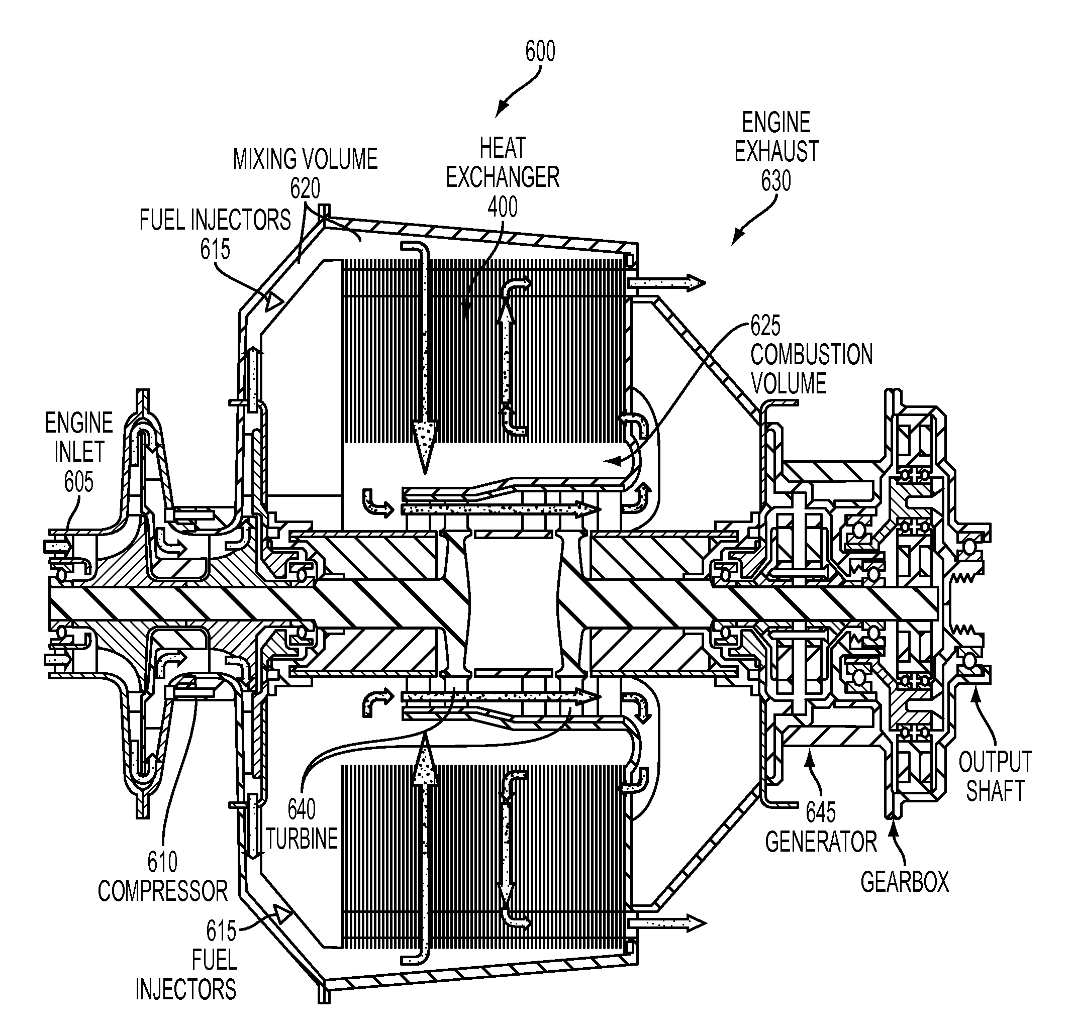
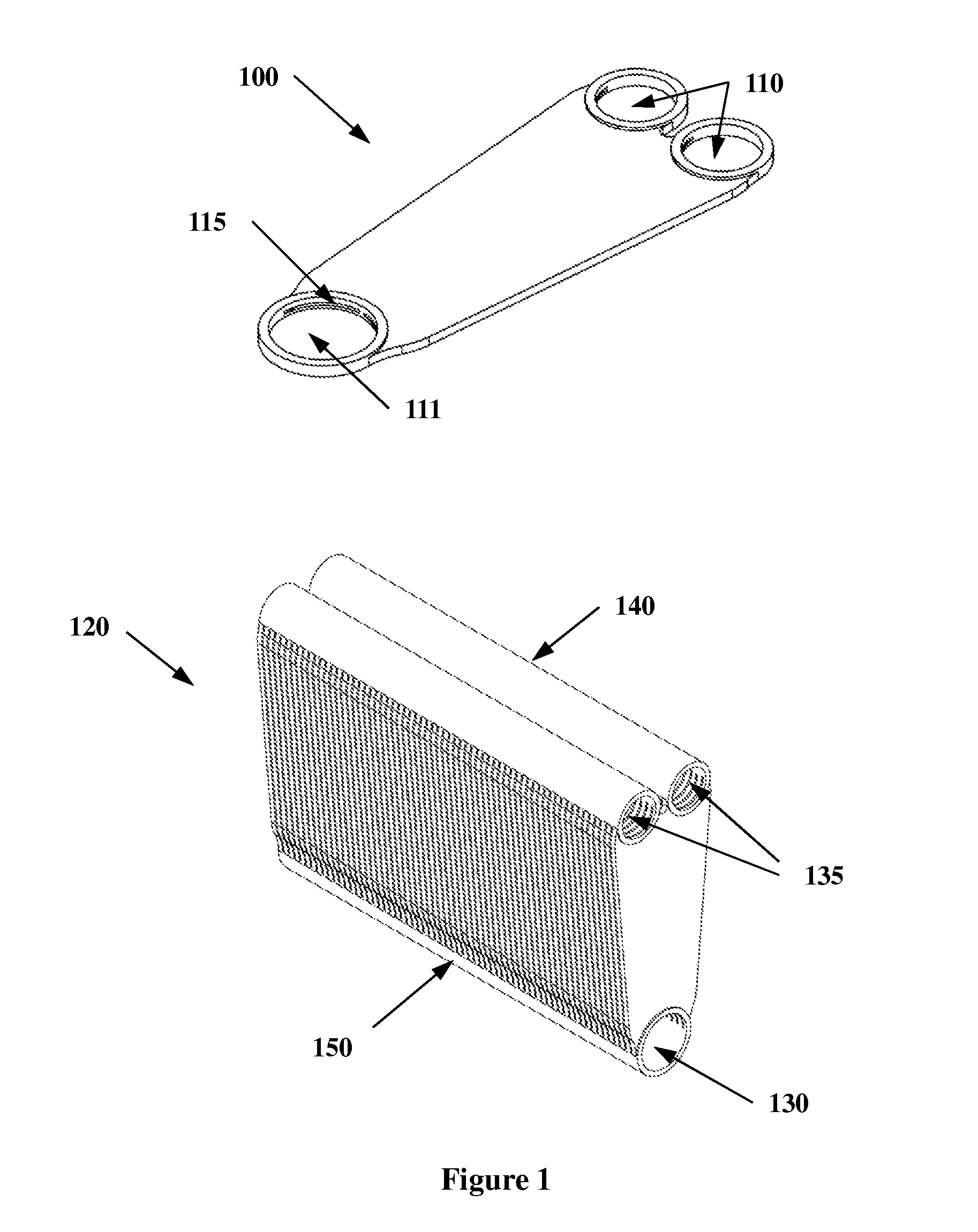
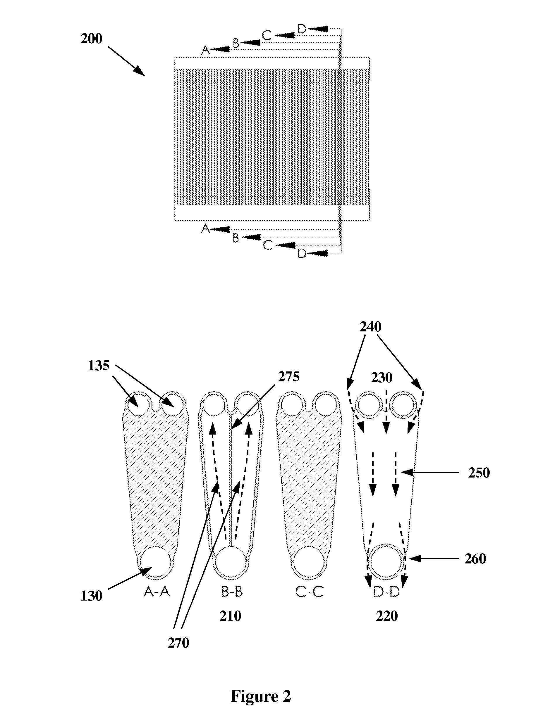
[0021]To overcome the limitations of the prior art, a heat exchanger assembly for gas-to-gas heat transfer is described herein. The device, having been designed for use as a recuperator in a miniature gas turbine engine and being particularly suitable for that application, will be described in that context. However, it will be obvious to one of ordinary skill in the art that a heat exchanger of different size or proportions, but similar in all fundamental aspects, could be useful in a number of other applications; for example, industrial furnaces, high temperature chemical process reactors, other types of recuperated engines, and the like. Thus in the following description, one gas stream is described as “compressed air”, in accordance with the gas turbine application, while the other stream is described as “ex...


PUM


Abstract

An annular design heat exchanger is formed from an arrangement of wedge-shaped stacks of wafers. Each wafer includes sheets of material separated by peripheral and supporting walls that define interior flow channels through which a first fluid can flow. Holes in the sheets provide inlets and outlets to the channels, and walls surrounding the holes mate with neighboring wafers in the stack, forming integral inlet and outlet manifolds, while ensuring uniform spacing between the wafers. A second fluid can flow around the manifolds and through the spaces between the wafers in a counterflow pattern. In the annular assembly, the manifolds are oriented substantially axially, and the flow channels are oriented substantially radially. The heat exchanger can be formed from a ceramic material, and can be incorporated into an engine assembly or a heat-recirculating combustor.

Description

CROSS-REFERENCE TO RELATED APPLICATIONS[0001]This application claims priority to provisional patent application entitled, “Compact Ultra-Lean Premixed Recuperated Combustor,” filed on May 22, 2009, and assigned U.S. Application No. 61 / 180,480; the entire contents of which are hereby incorporated by reference.FIELD OF THE INVENTION[0002]The invention relates generally to compact, high temperature gas-to-gas heat exchangers. More specifically, the invention relates to a radial counterflow recuperator, a type of heat exchanger, which is particularly suitable for waste heat recovery in a gas turbine engine.BACKGROUND[0003]Most gas turbines in service today are of the “simple cycle” type, which means they typically consist of only a compressor, a combustor (burner), and a turbine. In simple cycle engines, the exhaust leaving the turbine is still very hot. This rejection of unused heat to the atmosphere represents a waste of energy. For this reason, some gas turbines employ a heat exchang...

Claims


Application Information

Patent Timeline
Patent Type & Authority Patents(United States)
IPC IPC(8): F28F3/00F02C7/10
CPCF02C3/08F02C7/10F23D14/66F23L15/04F28D9/0043F28D9/0056F28F21/04F28D9/0018F05D2220/76Y02T50/671F28D21/0003Y02E20/34Y02T50/60
Inventor VICK, MICHAEL J.
Owner UNITED STATES OF AMERICA
Why Eureka
Try Eureka