Ultra high linearity amplifier

a high-linearity, amplifier technology, applied in differential amplifiers, amplifiers with semiconductor devices/discharge tubes, amplifier details, etc., can solve the problems of inability to achieve symmetrical tracking of power supplies, unmatched linearity that cannot be obtained by operating parts, etc., to improve linearity, improve linearity, and large output swing

Active Publication Date: 2007-08-28
KEYSIGHT TECH
View PDF3 Cites 1 Cited by
  • Summary
  • Abstract
  • Description
  • Claims
  • Application Information

AI Technical Summary

Problems solved by technology

The result is unmatched linearity that cannot be obtained by operating the part in the conventional manner.
The villain here would be either imperfect common mode rejection by the amplifier for its power supplies, or, failure of the tracking for the power supplies to be exactly symmetrical.

Method used


Image

  • Ultra high linearity amplifier
  • Ultra high linearity amplifier
  • Ultra high linearity amplifier

Examples


Embodiment Construction

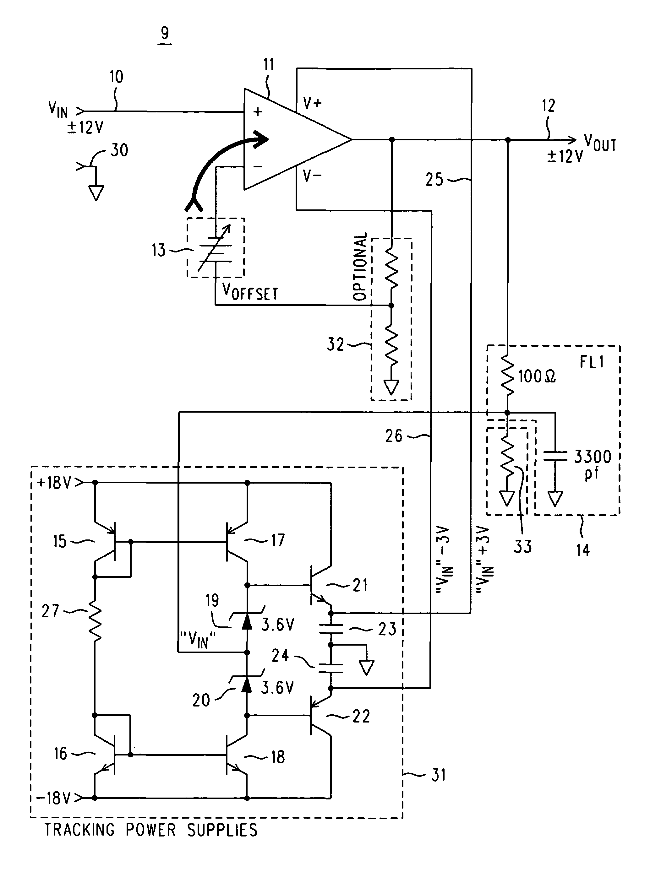
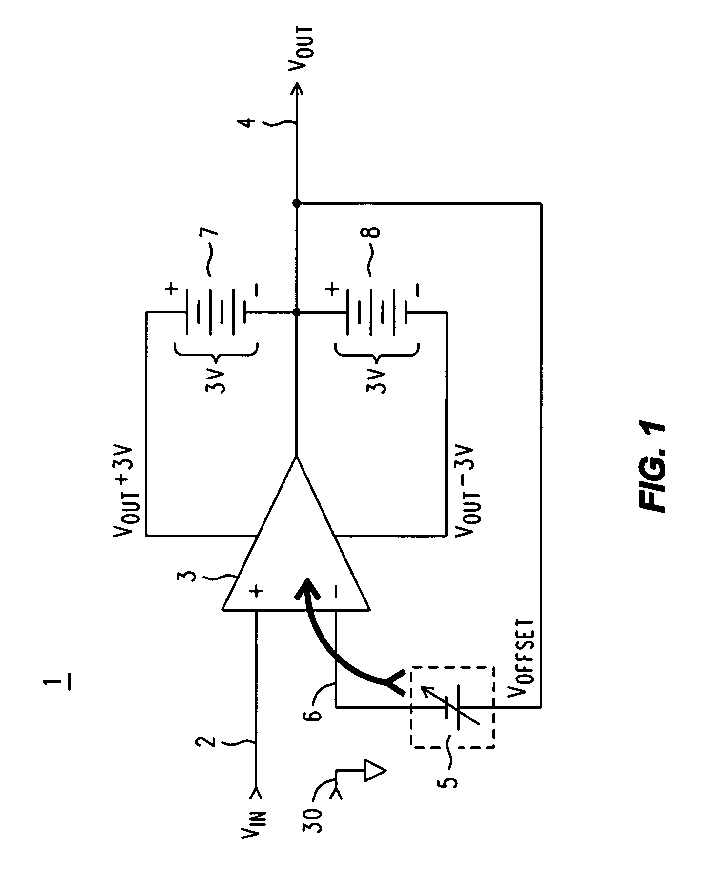
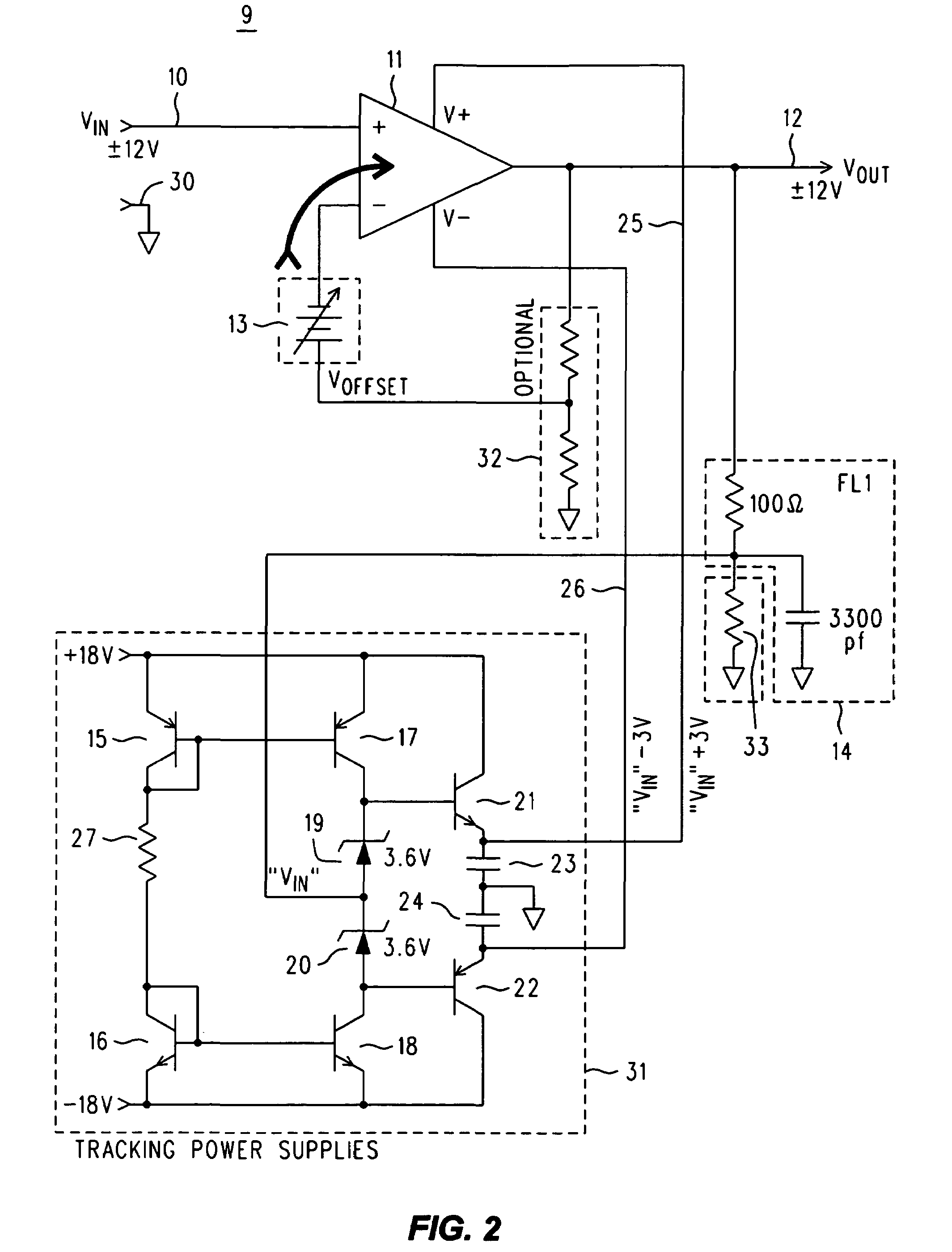
[0012]Refer now to FIG. 1, wherein is shown a simplified equivalent circuit diagram 1 useful in appreciating how a large swing unity gain amplifier with extremely high linearity can be realized using a low voltage differential amplifier. A conventional low voltage swing differential amplifier 3 has the usual plus (+) and minus (−) inputs, to which an input voltage VIN 2 (which is with respect to a ground 30) is applied at the plus input. The minus input is connected to the output VOUT (which is to be used elsewhere for whatever reason the unity gain amplifier is there in the first place . . . ). The variable VOFFSET supply 5 represents the equivalent source associated with the CMR mechanism within the amplifier 3. Were it not for the non-linearity associated with CMR, changes in the DC output would be expected to exactly track changes in the DC input, micro volt for micro volt, as it were. AC operation follows naturally, up to the point where the amplifier's frequency response begin...


PUM


Abstract

The output of a commercially available integrated high gain differential amplifier that already has reasonable linearity is connected back to the (−) input to obtain the well known circuit configuration for a non-inverting amplifier, whose gain may be unity or greater, and whose linearity in response to the (+) input is to be improved. We operate the part with power supplies that are dynamically varied to always be the amplifier input+N volts and that input−N volts. This allows the part to remain a low voltage swing part (±N volts) even though the actual output might swing several times that ±N volts. It improves linearity because the part is almost always operating at nearly ‘the same operating point’ relative to the perceived power supplies. The dynamically tracking power supplies maybe obtained from plus and minus higher voltage work supplies and the use of symmetrical current mirrors to produce matched ±N volt offsets that are referenced to the input of the amplifier.

Description

BACKGROUND OF THE INVENTION [0001]There are many electronic applications for a unity gain amplifier, which manner of electronic circuit is also often referred to as a unity gain buffer, as well as for amplifiers that have a gain greater than unity. One application that places relatively high demands for good performance upon such an amplifier or buffer is at the ‘front end’ of a laboratory quality high accuracy DC DVM (Digital Volt Meter). Nowadays, high accuracy usually means seven to nine digits of resolution, with perhaps just a few counts of error in the least significant digit. Most DC DVMs also measure AC with reduced accuracy for pure sinusoids having frequencies up to about one to, in some cases, as high as ten megahertz. The ‘front end’ of a DVM is a location therein after any input attenuation, but before the actual measurement mechanism.[0002]It is immediately clear that any unity gain buffer in such a location does indeed have stringent performance requirements, since it...

Claims


Application Information

Patent Timeline
Patent Type & Authority Patents(United States)
IPC IPC(8): H03F3/45
CPCH03F1/3211H03F3/45475H03F3/45973H03F2200/261H03F2200/504H03F2203/45136H03F2203/45138
Inventor COLEY, WILLIAM H.VENZKE, STEPHEN B.
Owner KEYSIGHT TECH
Why Eureka
Try Eureka