
Computing water saturation in laminated sand-shale when the shale are anisotropic

Active Publication Date: 2007-08-28
SCHLUMBERGER TECH CORP
View PDF2 Cites 15 Cited by
  • Summary
  • Abstract
  • Description
  • Claims
  • Application Information

AI Technical Summary

Benefits of technology

This approach provides accurate water saturation calculations, avoiding false conclusions about hydrocarbon presence and improving the estimation of hydrocarbon reserves by correctly accounting for shale anisotropy in resistivity measurements.

Problems solved by technology

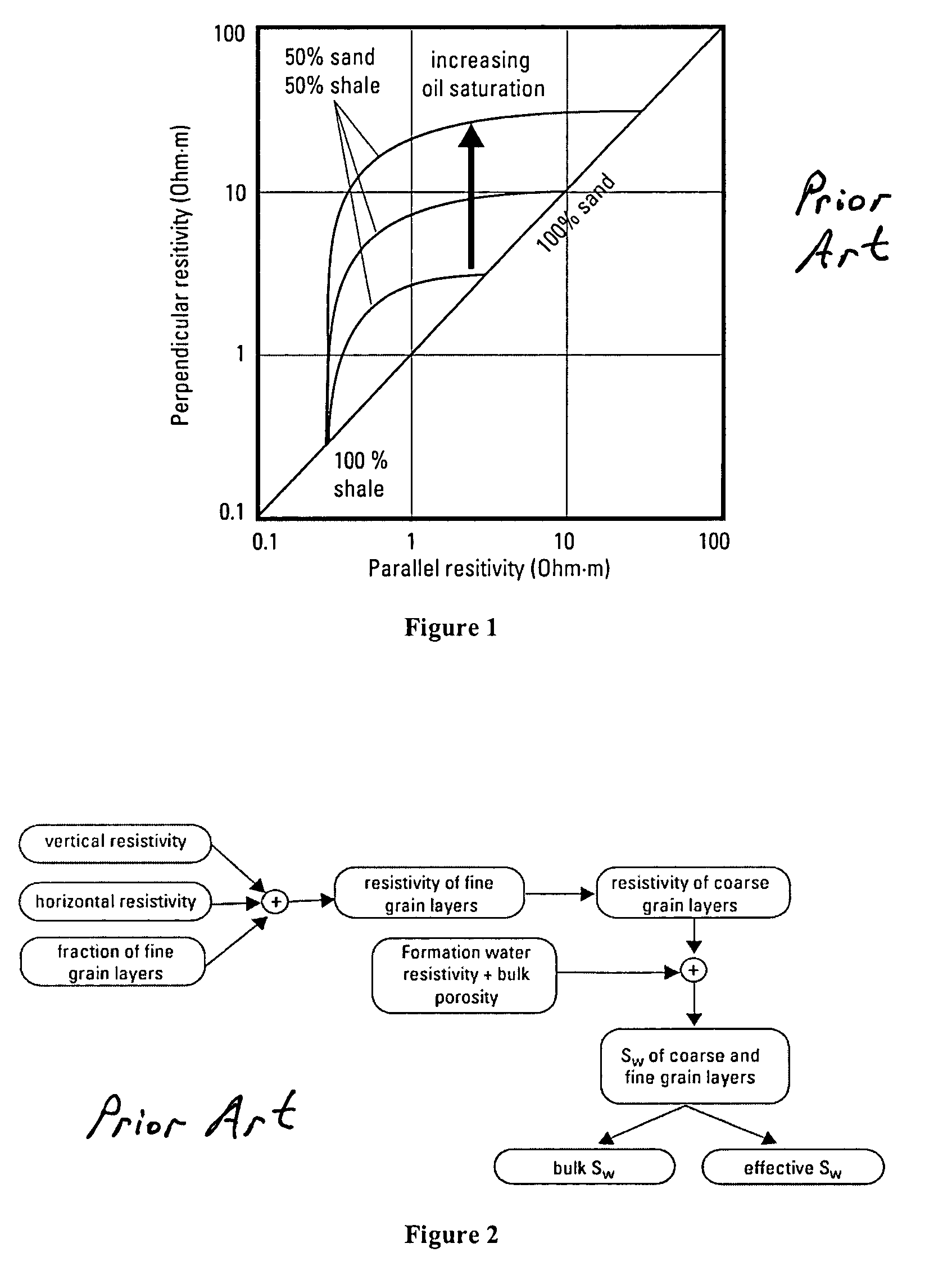
A limitation of those two approaches is that they assume each layer is individually isotropic (i.e., Rv and Rh are equal in each layer).

Method used


Image

  • Computing water saturation in laminated sand-shale when the shale are anisotropic
  • Computing water saturation in laminated sand-shale when the shale are anisotropic
  • Computing water saturation in laminated sand-shale when the shale are anisotropic

Examples


Embodiment Construction

[0016]The present invention is a modeling method using a set of equations during or after logging operations to take into account the intrinsic electrical anisotropy of shale when computing water saturation in laminated shale-sand formations. The computation of water saturation in earth formations is useful at least for pay / reserve quantification, oil / water contact detection, relative permeability estimation, and reservoir simulation.

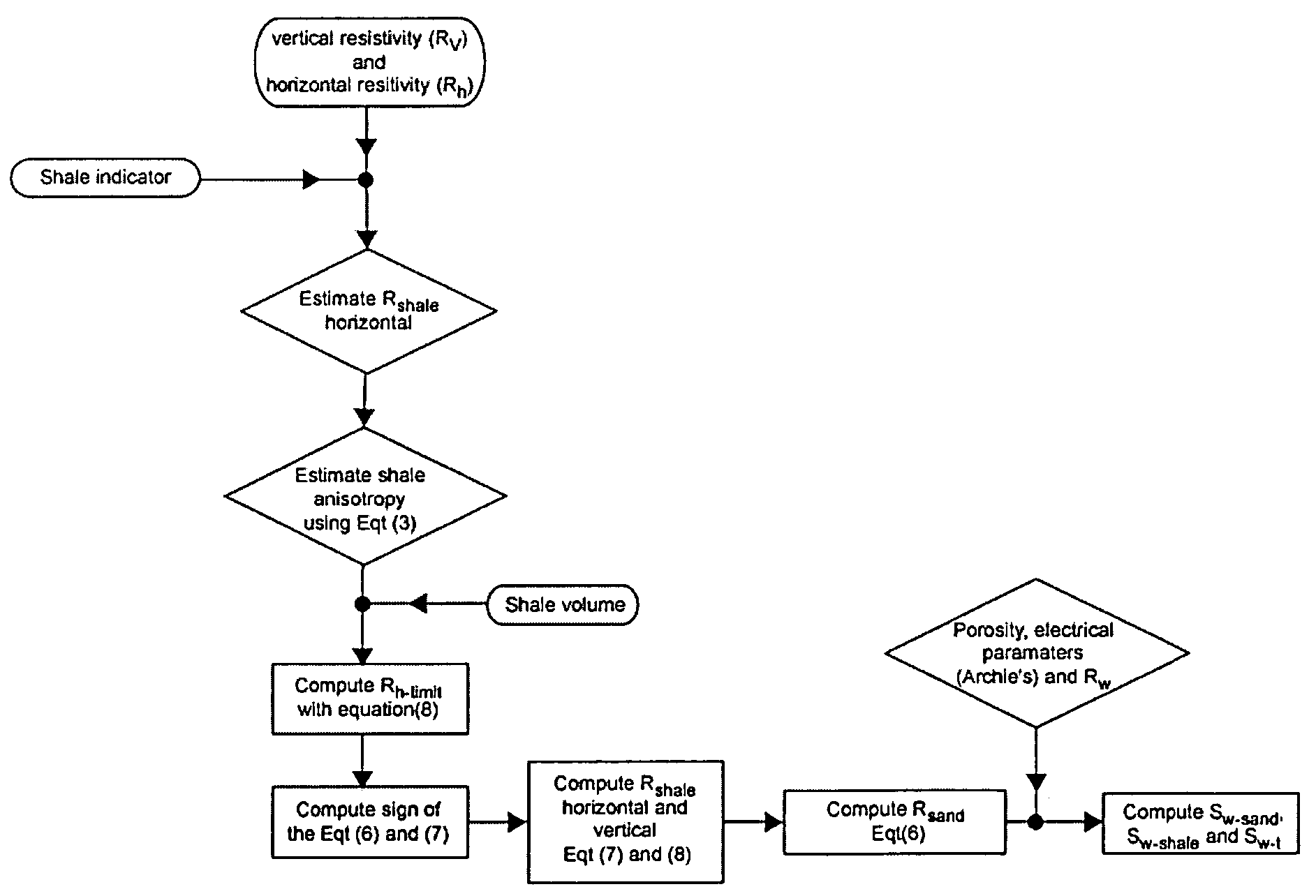
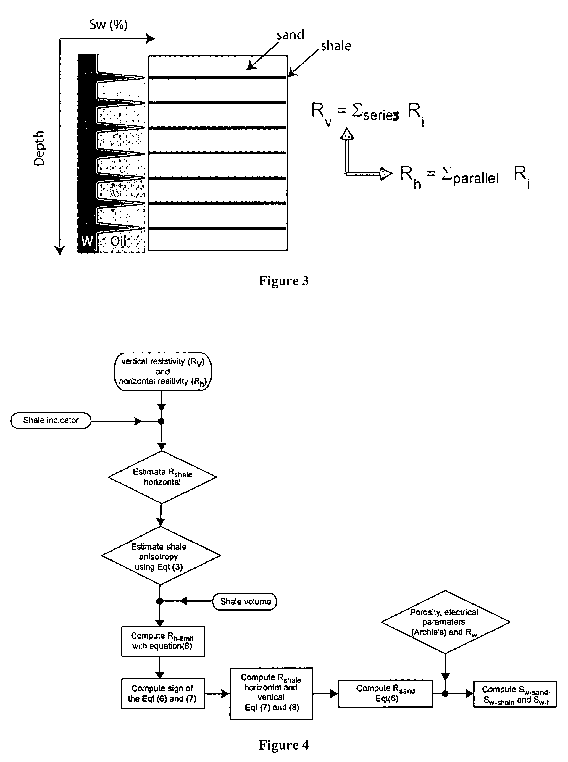
[0017]The method makes use of anisotropy of resistivity measurements. The computation allows one to take the shale anisotropy into account to better estimate water saturation Sw. The computation is based on the inversion of the anisotropy of resistivity in thin-bedded laminated sand-shale in terms of shale and sand resistivities. A shale anisotropy term is used to obtain the correct resistivity for both the sand and the shale. Consequently, the correct water saturation Sw can be computed for the sand, the shale, and the (total) formation.

[0018]Thinly la...


PUM


Abstract

A method to determine water saturation of laminated sand-shale formations based on measurements of formation and shale resistivity anisotropy, the fraction of shale, and the porosity.

Description

CROSS-REFERENCE TO RELATED APPLICATIONS[0001]This application claims priority, under 35 U.S.C. § 119, to Provisional Application Ser. No. 60 / 618,668, filed Oct. 14, 2004, incorporated by reference in its entirety.BACKGROUND OF THE INVENTION[0002]1. Field of Invention[0003]This invention pertains to techniques for determining characteristics of earth formations and, more particularly, to techniques to determine water saturation in laminated shale-sand formations from measurements of resistivity anisotropy.[0004]2. Related Art[0005]Electrical anisotropy has been used to detect low-resistivity, low-contrast pay zones such as can occur in thin-bed formations. A water-wet formation with large variability in grain size can be highly anisotropic in the oil-bearing portion and isotropic in the water-bearing portion. The resistivity anisotropy is generally attributed to grain-size variations that affect irreducible water saturation between the laminations. Thin, interbedded sandstones, silts...

Claims


Application Information

Patent Timeline
Patent Type & Authority Patents(United States)
IPC IPC(8): G01V3/38
CPCE21B49/00G01V3/20G01V9/02G01N15/08
Inventor CLAVAUD, JEAN-BAPTISTE
Owner SCHLUMBERGER TECH CORP
Learn More