Hydraulic circuit and its valve gear

a technology of valve gear and circuit, applied in the field of hydraulic circuit, can solve the problems of complicated circuit structure and formation of path structure, and achieve the effect of reducing the number of processing in the hold of the valve gear

Inactive Publication Date: 2007-09-04
NABLESCO CORP
View PDF10 Cites 10 Cited by
  • Summary
  • Abstract
  • Description
  • Claims
  • Application Information

AI Technical Summary

Benefits of technology

[0007]The present invention has been made taking the foregoing problems into consideration and the object of the invention is to provide a simple circuit structure and a simple path structure and a compact valve gear in a hydraulic circuit having a pilot check valve and an overload relief valve and its valve gear.

Problems solved by technology

Therefore, this involves a problem such that the circuit structure is complicated as the hydraulic circuit and the structure of the path formed in the valve gear is complicated.

Method used


Image

  • Hydraulic circuit and its valve gear
  • Hydraulic circuit and its valve gear
  • Hydraulic circuit and its valve gear

Examples


first embodiment

of the Hydraulic Circuit

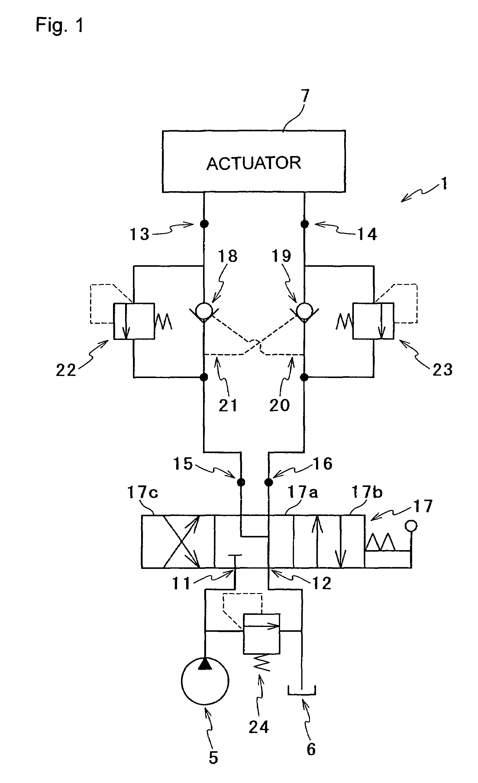
[0028]FIG. 1 shows a hydraulic circuit according to a first embodiment of the invention. For example, this hydraulic circuit 1 is used as that for driving various actuators in a construction machine or the like. Then, this hydraulic circuit 1 is connected to a pump 5, a tank 6, and an actuator 7, and this hydraulic circuit 1 is configured as a hydraulic circuit which returns the hydraulic oil supplied from the pump 5 to the tank 6 via the actuator 7 and circulates the hydraulic oil to control the operation of the actuator 7.

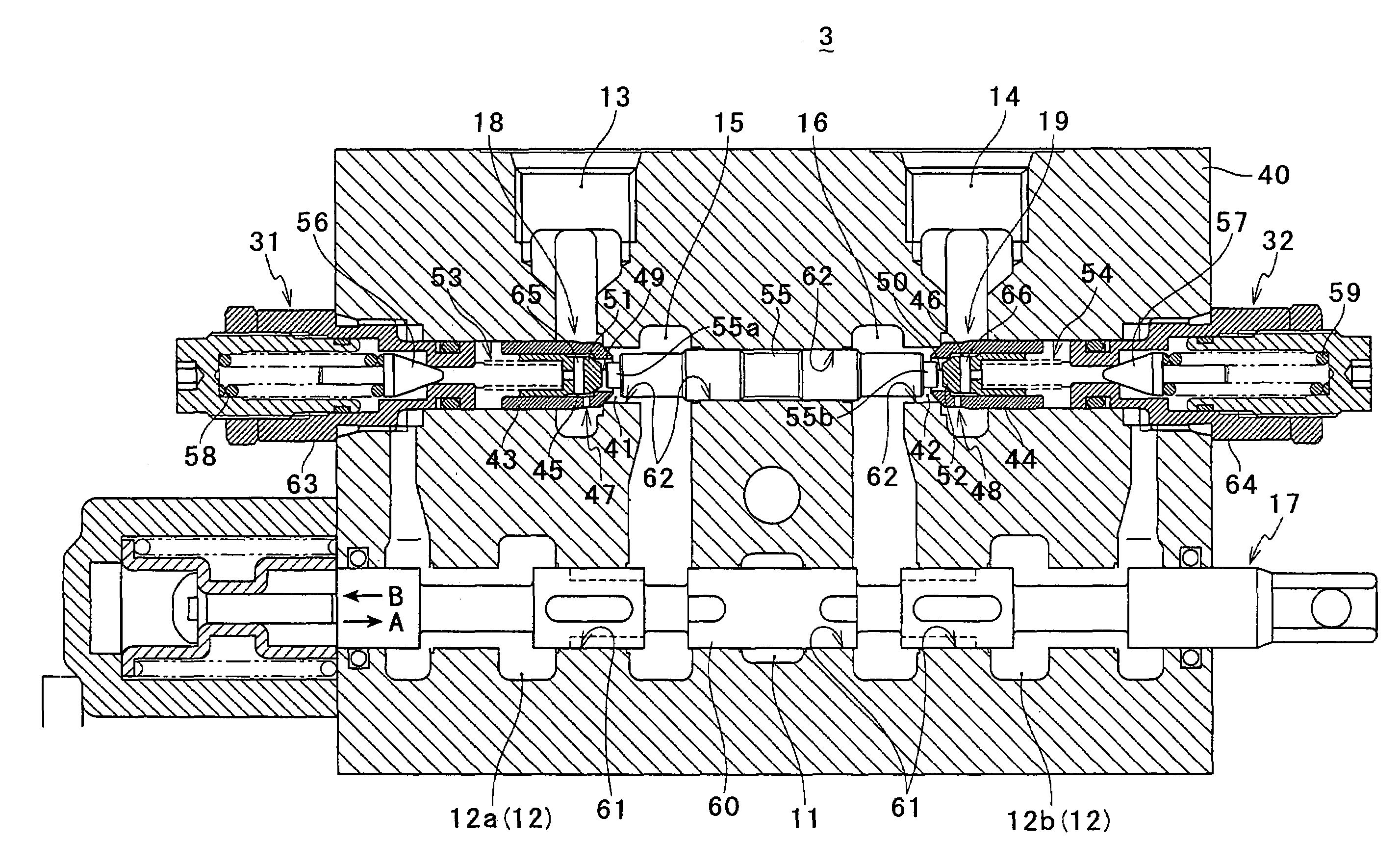
[0029]This hydraulic circuit 1 is provided with various ports such as a pump port 11, a tank port 12, a first actuator port 13, a second actuator port 14, a first supply and discharge port 15, and a second supply and discharge port 16. The pump port 11 is connected to the pump 5 so as to be communicated therewith, and the tank port 12 is connected to the tank 6 so as to be communicated therewith. In addition, the first actuator port 13 and...

second embodiment

of a Hydraulic Oil Circuit

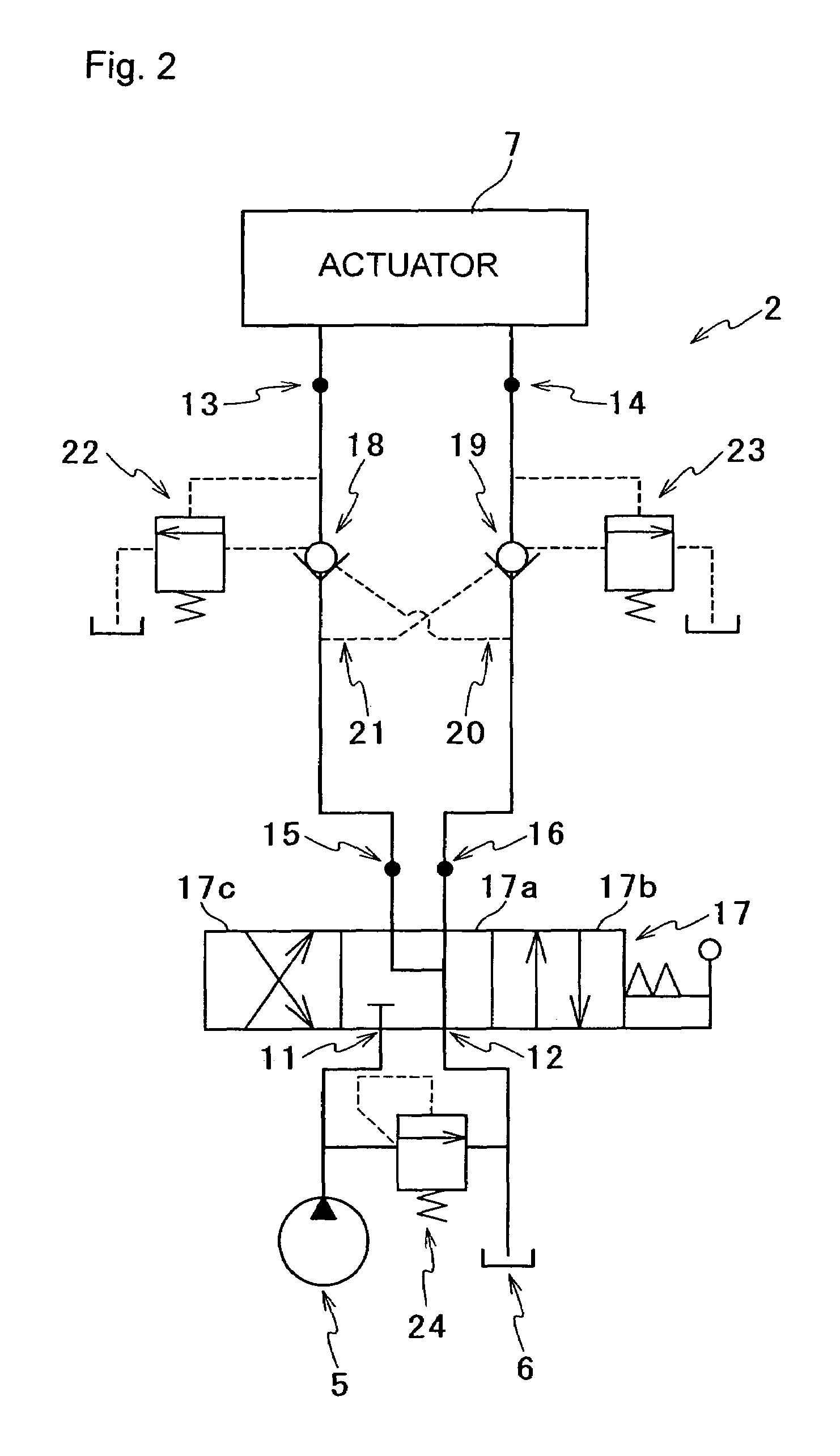
[0046]FIG. 2 shows a hydraulic circuit according to a second embodiment of the invention. As same as the hydraulic circuit 1 of the first embodiment, this hydraulic circuit 2 is also used as a hydraulic circuit to drive various actuators in a construction machine or the like as same as the hydraulic circuit 1 of the first embodiment. Then, this hydraulic circuit 2 is also connected to the pump 5, the tank 6, and the actuator 7, and this hydraulic circuit 2 is configured as a hydraulic circuit which returns the hydraulic oil supplied from the pump 5 to the tank 6 via the actuator 7 and circulates the hydraulic oil to control the operation of the actuator 7.

[0047]This hydraulic circuit 2 is also provided with the pump port 11, the tank port 12, the first actuator port 13, the second actuator port 14, the first supply and discharge port 15, the second supply and discharge port 16, the direction changing valve 17, the first pilot check valve 18, the second pilo...


PUM


Abstract

To simplify a circuit structure and a path structure in a hydraulic circuit having a pilot check valve and an overload relief valve and to reduce the size of a gear. The hydraulic circuit includes a pump port; a tank port; a first actuator port; a second actuator port; a first supply and discharge port; a second supply and discharge port; a direction changing valve; a first pilot check valve; a second pilot check valve; a first pilot path; and a first overload relief valve. The direction changing valve has a neutral position to communicate the first supply and discharge port with the tank port. The first overload relief valve is arranged in parallel with the first pilot check valve and is arranged between the first supply and discharge port and the first actuator port.

Description

BACKGROUND OF THE INVENTION[0001]1. Field of the Invention[0002]The present invention relates to a hydraulic circuit having a direction changing valve that changes supply and discharge directions of hydraulic oil between a pump, a tank, and an actuator, a pilot check valve, and an overload relief valve, and its valve gear.[0003]2. Description of the Related Art[0004]Conventionally, a hydraulic circuit having a direction changing valve for changing supply and discharge directions of hydraulic oil between a pump, a tank, and an actuator, a pilot check valve arranged between the direction changing valve and the actuator, and an overload relief valve for discharging the excess hydraulic oil; and its valve gear have been known (refer to Patent document 1). In the hydraulic circuit and the valve gear described in this Patent document 1, the pilot check valve (a lock valve mechanism v in Patent document 1) and the overload relief valve (a relief valve 40 in Patent document 1) are communica...

Claims


Application Information

Patent Timeline
Patent Type & Authority Patents(United States)
IPC IPC(8): F15B11/00F16K17/00
CPCF15B11/044F15B2211/20538F15B2211/3051F15B2211/31576F15B2211/324F15B2211/50518F15B2211/50536F15B2211/5059F15B2211/5151F15B2211/5153Y10T137/87185F15B11/00
Inventor IOKU, KENSUKE
Owner NABLESCO CORP
Why Eureka
Try Eureka