Supercharge Your Innovation With Domain-Expert AI Agents!

Valve with offset venturi

Inactive Publication Date: 2007-09-04
VICTAULIC
View PDF50 Cites 10 Cited by
  • Summary
  • Abstract
  • Description
  • Claims
  • Application Information

AI Technical Summary

Benefits of technology

[0004]The invention concerns a valve for controlling fluid flow. The valve comprises a housing having a bore extending therethrough, a valve seat and a valve closing member mounted within the bore. The closing member is movable between a closed position sealingly engaged with the seat, and an open position wherein the closing member divides the bore into first and second passageways. The

Problems solved by technology

While this configuration provides a compact design, the closeness of the venturi to the internal valve components does not allow accurate pressure measurements to be made from which the volumetric flow rate may be determined.
Turbulence in the flow through the valve caused by the valve closing member (a plate or disk in a butterfly valve) causes the pressure in the venturi to fluctuate randomly, thereby reducing the ability to make accurate pressure measurements, and hence adversely affects the flow rate determination.
The position and degree of turbulence is further varied in the venturi as the valve closing member is moved, making it difficult to adjust the position of the valve closing member in response to real time pressure measurements to obtain a desired flow rate.

Method used


Image

  • Valve with offset venturi
  • Valve with offset venturi
  • Valve with offset venturi

Examples


Embodiment Construction

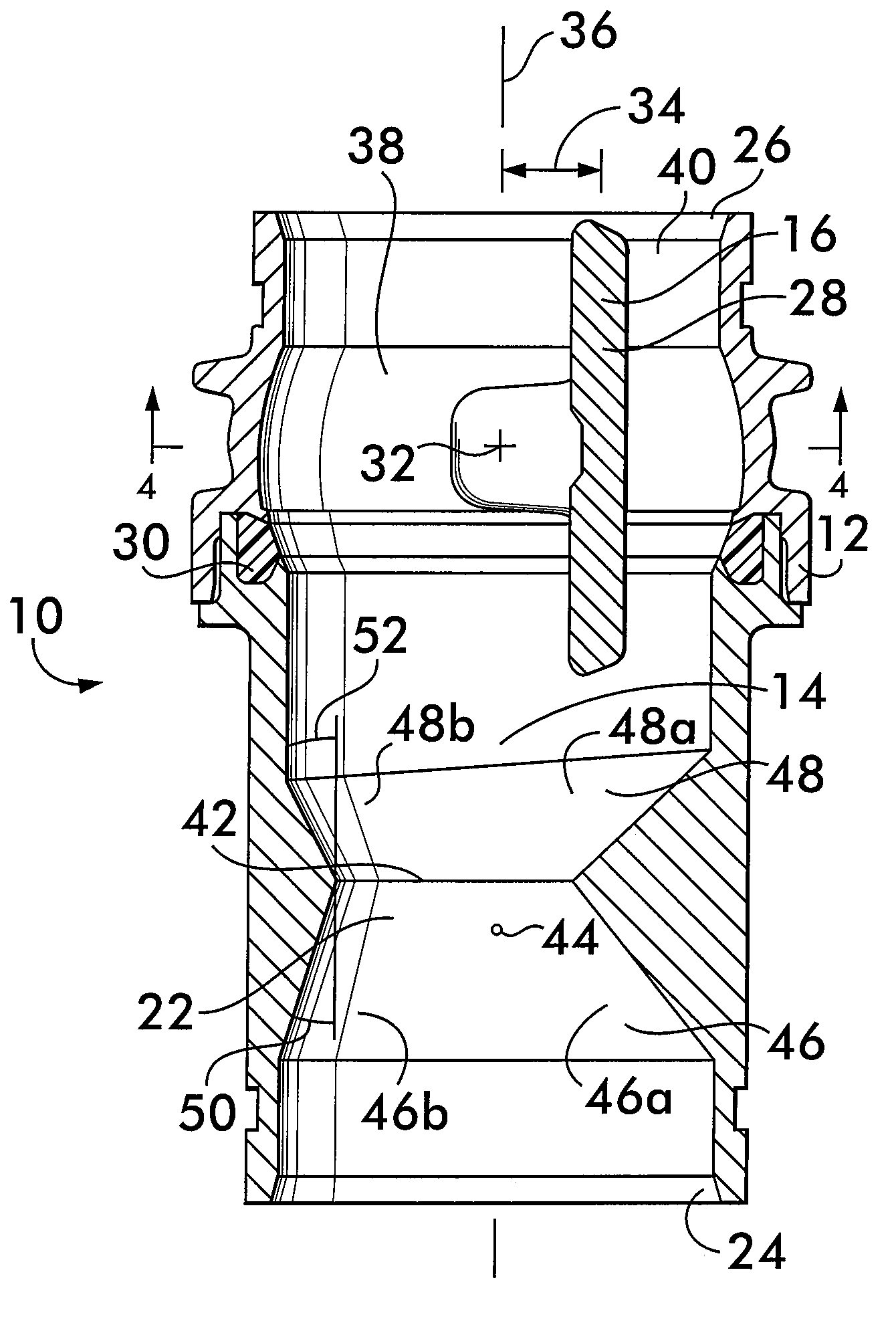
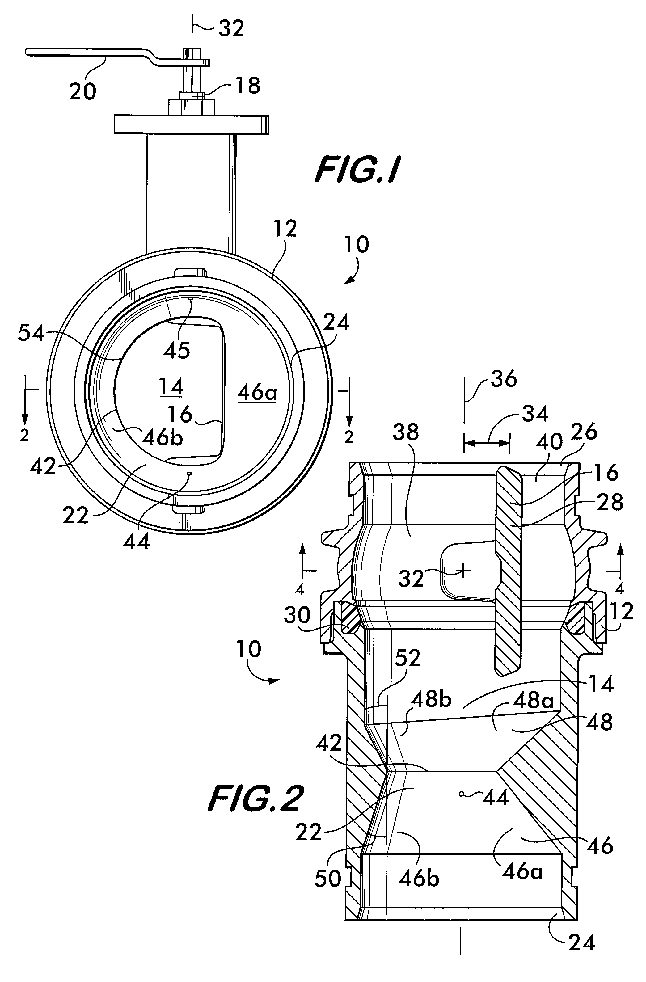
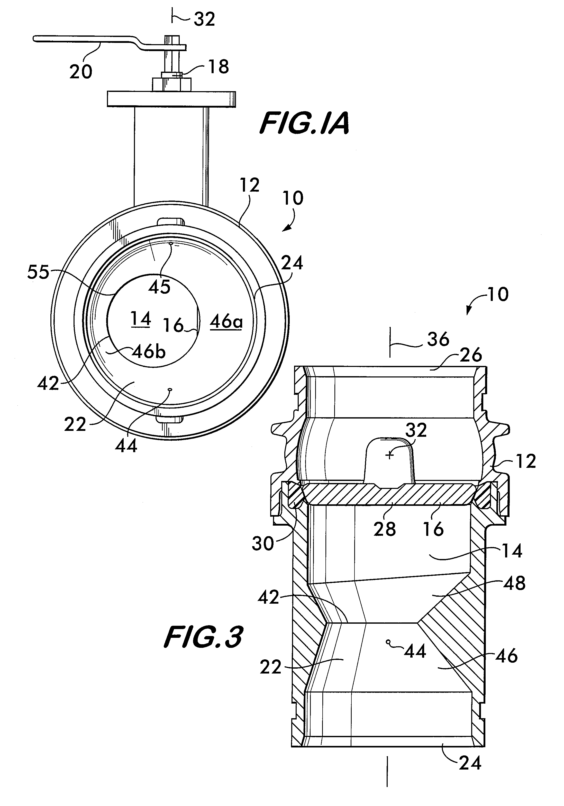
[0016]FIG. 1 shows a valve 10 according to the invention. Valve 10 comprises a housing 12 having a bore 14 therethrough. A valve closing member 16 (see also FIG. 4) is positioned within the housing. The closing member, described in detail below, is connected to an actuator, for example, valve stem 18 having a handle 20 for manual valve operation. A venturi 22 is positioned within the bore 14 between the valve inlet 24 and the valve closing member 16. An outlet 26, best shown in FIG. 2, is positioned downstream of the valve closing member.

[0017]In this example, the valve 10 is a butterfly valve having a closing member comprising a plate 28 rotatably mounted within the housing 12. As shown in FIGS. 2 and 3, the plate 28 is rotatable between a fully closed position (FIG. 3) wherein the plate sealingly engages a seat 30, and a fully open position (FIG. 2) wherein the plate 28 is oriented substantially parallel to the fluid flow path through the bore 14. Seat 30 may comprise, for example...


PUM


Abstract

A valve is disclosed having a valve closing member that divides the valve bore into passageways of unequal cross sectional areas when in an open position. A venturi is positioned within the valve bore upstream of the valve closing member. The throat of the venturi may be within one pipe diameter of the valve closing member. The venturi is offset from the bore centerline so as to align with the larger of the two passageways. Turbulence is reduced allowing more accurate pressure measurements to be made within the venturi yielding more accurate determination of volumetric flow rates.

Description

FIELD OF THE INVENTION[0001]This invention relates to valves that incorporate a venturi to permit pressure measurements to be made for ascertaining flow rate therethrough.BACKGROUND OF THE INVENTION[0002]It is advantageous to combine a fluid flow rate measuring device with a valve. Such a device provides a compact means for precisely controlling the flow of fluid to readily establish a desired volumetric flow rate. One example of such a device is provided by positioning a venturi immediately upstream of a butterfly valve. Immediately upstream in this example means that the venturi is located within one or two pipe diameters of the valve closing member. While this configuration provides a compact design, the closeness of the venturi to the internal valve components does not allow accurate pressure measurements to be made from which the volumetric flow rate may be determined. Turbulence in the flow through the valve caused by the valve closing member (a plate or disk in a butterfly va...

Claims


Application Information

Patent Timeline
IPC IPC(8): F16K1/18
CPCF16K1/18F16K1/222F16K27/0209Y10S261/12Y10S261/56
Inventor WESTON, RICHARD R.
Owner VICTAULIC
Features
  • R&D
  • Intellectual Property
  • Life Sciences
  • Materials
  • Tech Scout
  • Unparalleled Data Quality
  • Higher Quality Content
  • 60% Fewer Hallucinations
Learn More