
Modular slotted drain assembly

a drain assembly and module technology, applied in sewer pipelines, applications, roads, etc., can solve the problems of time and labor intensive assembly of components, adverse effects on load bearing characteristics, etc., and achieve excellent load bearing properties, easy support of pedestrian and vehicular traffic, and increase the height of the drain assembly

Inactive Publication Date: 2007-09-04
HOUCK RANDALL J
View PDF14 Cites 55 Cited by
  • Summary
  • Abstract
  • Description
  • Claims
  • Application Information

AI Technical Summary

Benefits of technology

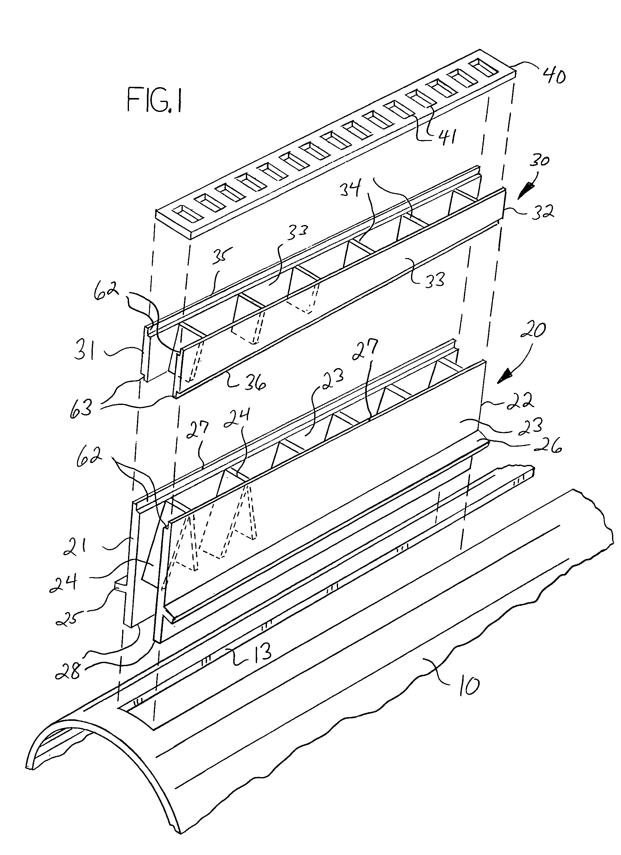
[0009]Mating means are provided to connect the reducer drain members to and above the base drain members. In a preferred embodiment the upper edges of the side walls of the base drain members and the lower edges of the side walls of the reducer drain members are joined using a mated rabbet or shiplapped joint. The upper edges of the reducer drain members are also provided with a corresponding rabbet, such that multiple reducer drain members may be vertically stacked to increase the height of the drain assembly. An apertured or slotted surface grate member may be retained by the upper rabbets of the uppermost reducer drain members to partially obstruct the drain opening. The modular drain assembly provides for excellent load bearing properties, such that pedestrian and vehicular traffic is easily supported.

Problems solved by technology

A problem associated with such systems results from the fact that the drainpipes are positioned in the ground so as to have a slight slope or incline to facilitate water flow, abut usually the slope of the ground surface does not correspond to the slope of the drainpipes.
These solutions require time and labor intensive assembly of components, and any load bearing characteristics are adversely affected by these assemblies.

Method used


Image

  • Modular slotted drain assembly
  • Modular slotted drain assembly
  • Modular slotted drain assembly

Examples


Embodiment Construction

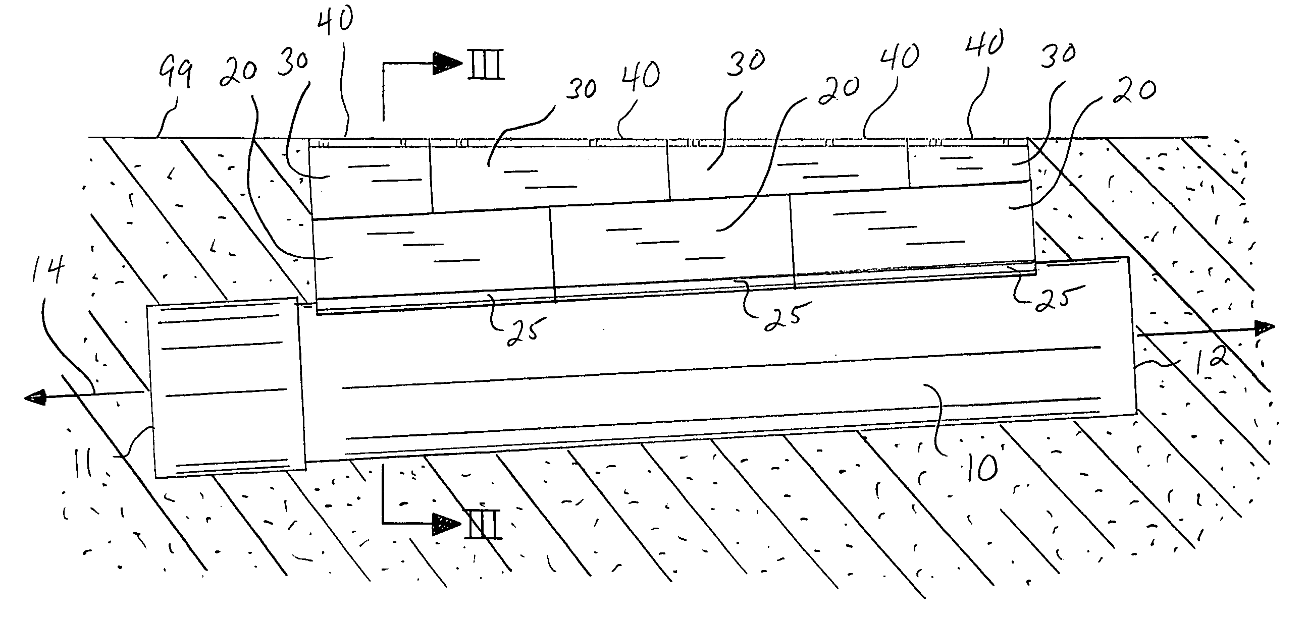
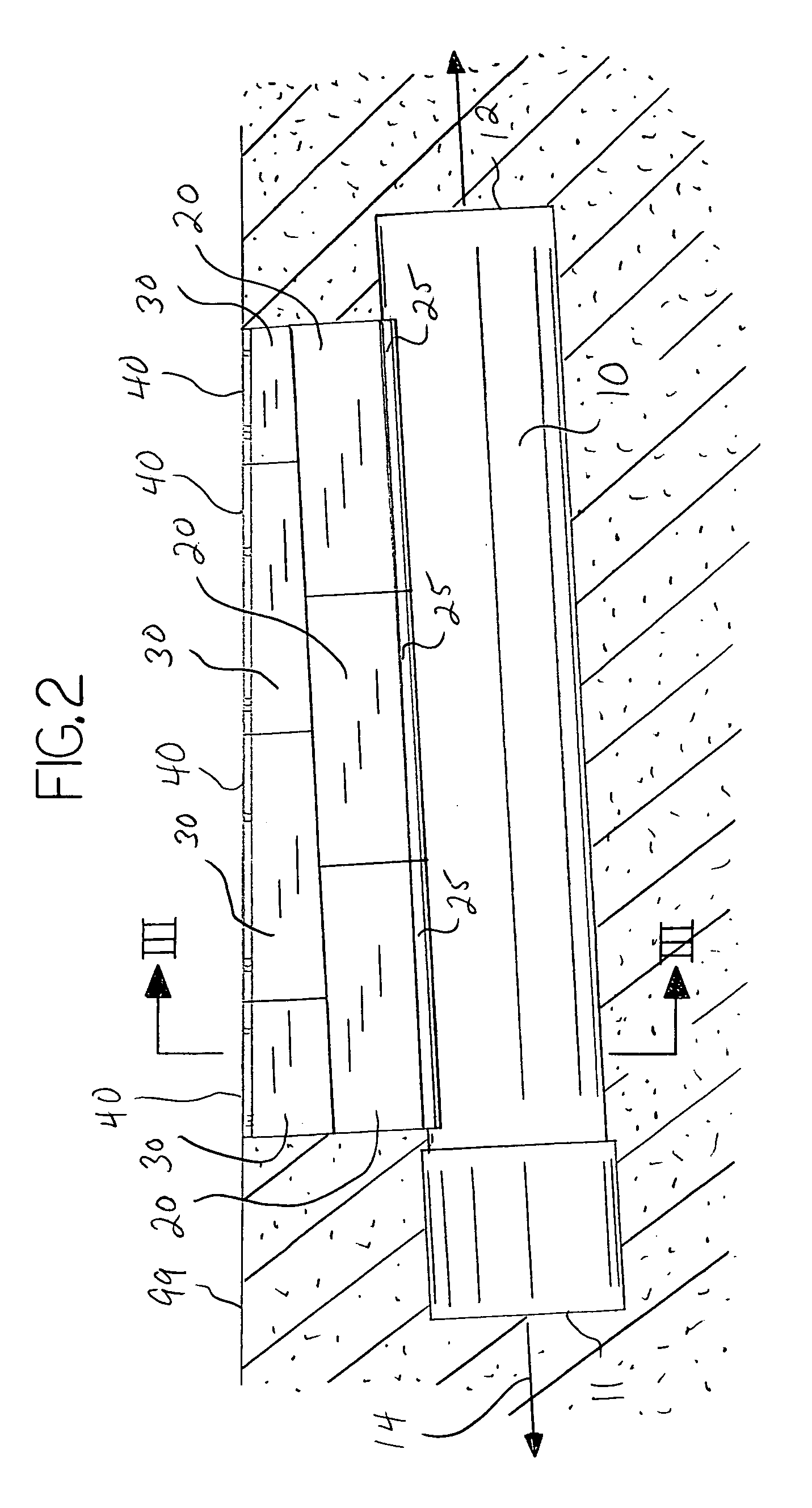
[0015]With reference to the drawings, the invention will now be described in detail with regard for the best mode and the preferred embodiment. In general, the invention is a modular slotted drain assembly comprising at least one and preferably multiple drainpipes 10, at least one and preferably multiple base drain members 20, and at least one and preferably multiple reducer drain members 30, connected in a generally vertical, stacked orientation with the base drain member 20 mounted atop the drainpipe 10 and the reducer drain member 30 mounted atop the base drain member 20. The reducer drain members 30 are structured with non-parallel upper edges 35 and lower edges 36, such that a reduction ratio is defined whereby through selection of reducer drain members 30 having proper reduction ratios, the incline or slope of the drainpipe 10 is translated so that the slope of the upper edges 36 of the uppermost reducer drain members 30 are parallel to the slope of the ground surface 99, the ...


PUM


Abstract

A modular slotted drain assembly having a slotted drainpipe, one or more base drain members positioned in communication with the slot of the drainpipe, and one or more reducer drain members stacked atop the base drain members. The reducer drain members have non-parallel upper and lower edges, such that one end of a reducer drain member is taller than its other end. An assembly is created such that the slope of the upper edges of the reducer drain members is not parallel to the drainpipe axis, allowing the upper edges of the reducer drain members to correspond to the slope of the ground surface.

Description

BACKGROUND OF THE INVENTION[0001]This invention relates generally to surface drains of the type used to remove accumulated or flowing water from roadways, parking lots, playing fields, runways or the like, and more particularly to surface drains often referred to as slotted drains, where an elongated drain extends from the surface to underground drainpipes, the drain mating with or received by an elongated longitudinal slot disposed in the upper portion of the drainpipe. More particularly, the invention relates to such drains where the height and / or slope of the drain can be varied or adjusted to account for the depth and / or the slope of the drainpipe relative to the surface.[0002]It is well known to provide extensive underground conduit systems for the removal of large quantities of surface water resulting from rain or other events. Such systems are typically necessary where the natural ground surface has been altered by building, paving or the like, such that rainwater cannot be a...

Claims


Application Information

Patent Timeline
Patent Type & Authority Patents(United States)
IPC IPC(8): E02B11/00
CPCE01C11/227E03F3/046Y02A30/60
Inventor HOUCK, RANDALL J.
Owner HOUCK RANDALL J
Learn More