Continuous electric power supply device

a technology of electric power supply and continuous power supply, which is applied in the direction of insulating conductors, cables, and cable arrangements between relatively moving parts, etc., can solve the problems of wire harness wear and damage, spiral springs that cannot be shrunk smoothly, and convex portion of spiral springs not being fitted into a concave portion of protectors

Inactive Publication Date: 2007-09-04
YAZAKI CORP
View PDF19 Cites 19 Cited by
  • Summary
  • Abstract
  • Description
  • Claims
  • Application Information

AI Technical Summary

Benefits of technology

[0017]To overcome the above drawback, an object of this invention is to provide a continuous electric power supply device that can miniaturize a device structure such as a protector, and absorb slack of a wire harness smoothly, and increase bending durability of the wire harness.How to Attain the Object
[0050]According to the device mentioned above, two types of protecting tubes with different materials and different shape can be connected together easily and securely with the connecting member, and the wire harness is structured. The connecting member may be fixed on one protecting tube by insert-molding so as to have a holding portion for the other protecting tube.

Problems solved by technology

A large bending stress is loaded on the wire harness, so that the wire harness would have time-dependent wear and damage.
Therefore, the spiral spring cannot be shrunk smoothly.
According to the device mentioned above, even if trying to mount the spiral spring oppositely on the protector, a convex portion of the spiral spring is not fitted into a concave portion of the protector.
Thereby, the spiral spring can not be mounted and prevented from an error of mounting.

Method used


Image

  • Continuous electric power supply device
  • Continuous electric power supply device
  • Continuous electric power supply device

Examples


first embodiment

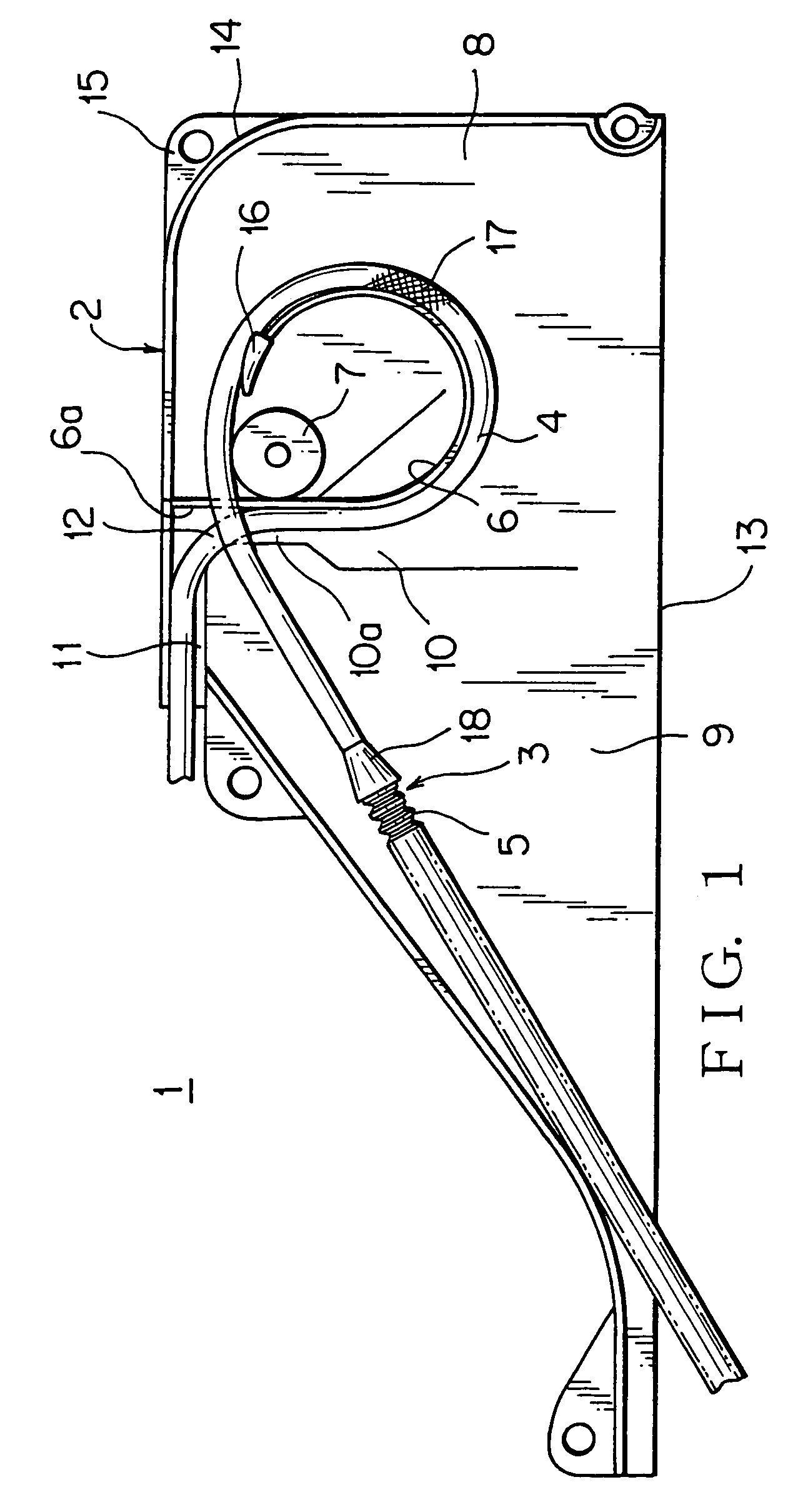
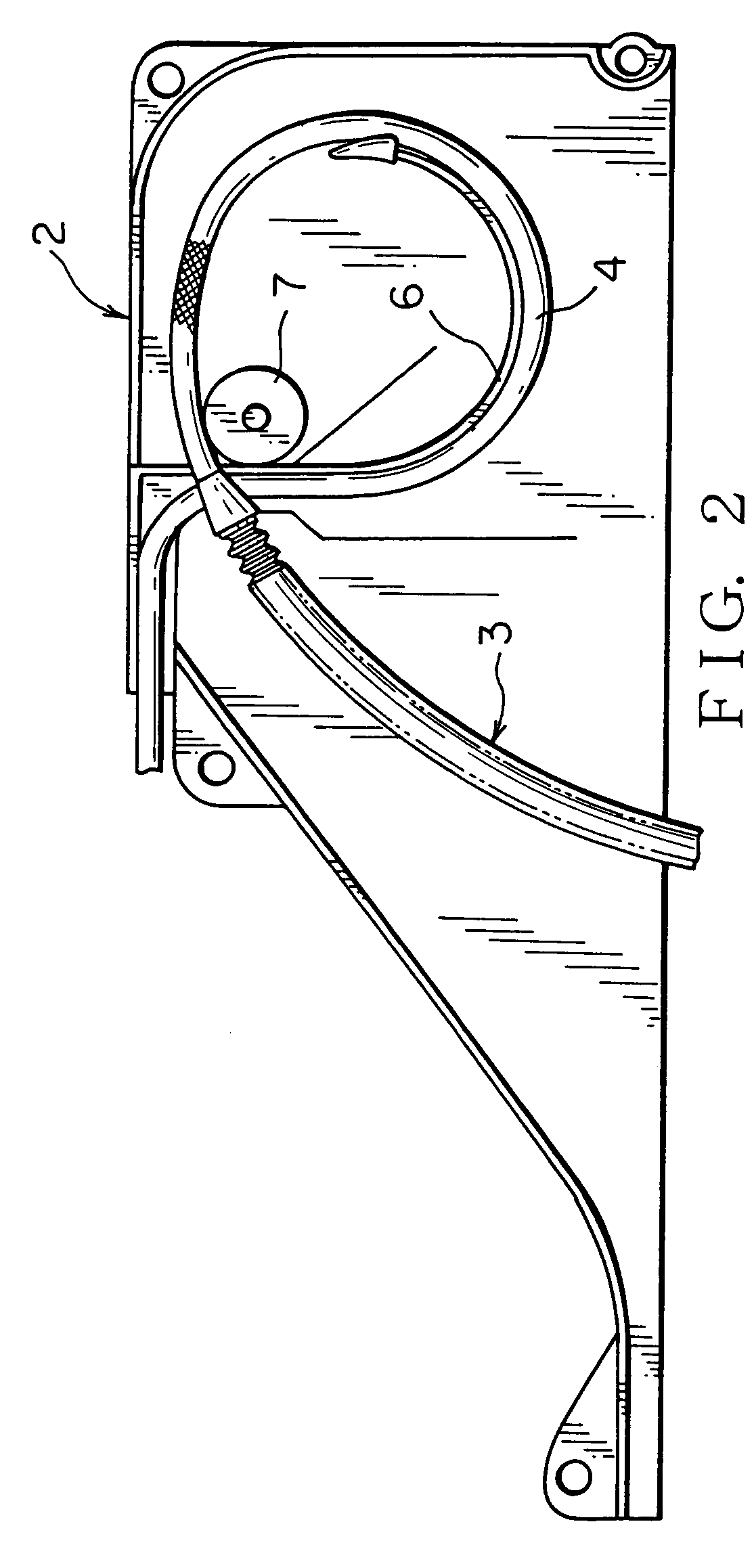
[0073]FIG. 1–3 show a continuous electric power supply device according to the present invention. FIG. 1 shows the device in a completely closed door, and FIG. 3 shows the device in a full opened door.

[0074]The continuous electric power supply device 1 is applied in a slide structure such as a slide door of a vehicle and includes a synthetic resin protector 2, a metallic flat spring 6 (elastic member) disposed along a wire harness 3 formed into a loop shape in a protector 2, and a guide roller 7 (guide portion) for supporting a loop portion 4 of of the wire harness 3 in the protector 2.

[0075]The protector 2 is formed in low profile to have a lower total height than a usual protector (FIG. 19). The protector 2 is provided with a base mounted on a panel of the slide door and a cover locked freely to open and close with the base by a lock device. In each embodiment, the base is shown, but the cover is not shown.

[0076]The protector 2 has a recess 10 recessing to spread in a fan shape fr...

second embodiment

[0103]FIG. 5–8 show the continuous electric power supply device according to this invention. The same structural parts as the above embodiment are put with the same marks without description.

[0104]A continuous electric power supply device 23 is applied for a slide structure such as a slide door of a vehicle, and includes a synthetic resin protector 2, a metal coil spring 24 disposed along an outer surface of the wire harness 3 formed into a loop shape in the protector 2 and a guide roller 7 (guide portion) supporting the loop portion 4 of the wire harness 3 in the protector 2. The structure of the protector 2 is the same as that of the first embodiment.

[0105]Turning a relatively thin spring wire in coil shape with many turns forms the coil spring 24. A bottom end 24a of the coil spring 24 is fixed at a bottom end (fixed end) of the loop portion 4 of the wire harness 3 on the loop portion 4 or the protector 2. A top end 24b of the coil spring 24 is fixed at a top end (moving end) of ...

third embodiment

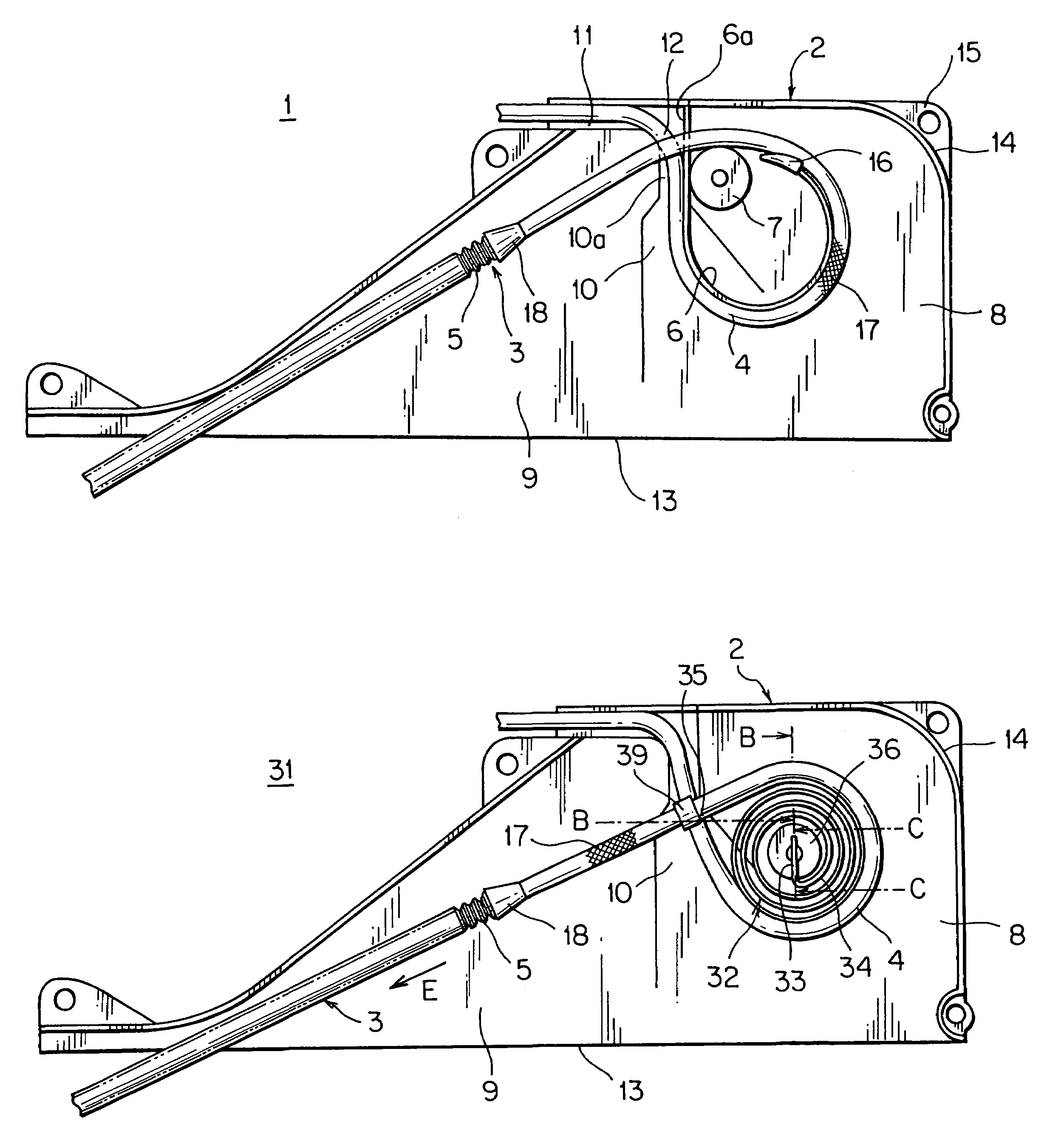
[0118]FIG. 11–14 show the continuous electric power supply device. FIG. 11 shows condition in the completely closed slide door. FIG. 12 shows condition in the partially opened slide door. FIG. 13 shows condition of the full opened slide door. FIG. 14 is a sectional view taken along the line B—B in FIG. 11.

[0119]This continuous electric power supply device 31 is applied for a slide structure such as a slide door of a vehicle as shown in FIG. 11–13, and includes a synthetic resin protector 2 and a metallic spiral spring 32 (elastic member) disposed in the wire harness 3 formed in loop shape in the protector 2.

[0120]The protector 2 has the same structure as that of the first embodiment, so that the same marks are putted and description is omitted. The spiral spring 32 can push uniformly the loop portion 4 of the wire harness 3 in the radial direction. Thereby, the aforesaid guide roller 7 can be eliminated.

[0121]The spiral spring made of a metallic band sheet includes a short straight ...


PUM

PropertyMeasurementUnit
stress concentrationaaaaaaaaaa
shapeaaaaaaaaaa
lengthaaaaaaaaaa

Abstract

For miniaturizing a power supply structure to absorb slack of a wire harness and improving bending durability, a continuous electric power supply device 1 includes a wire harness 3 formed to have a loop portion 4, an elastic member 6 along the loop portion 4, the elastic member energizing the loop portion to expand in a radial direction. The loop portion 4 and the elastic member 6 are disposed in a protector 2. The protector has a opening 13 for leading the harness and a guide portion 7 for supporting the loop portion 4 at a position opposite to the opening 13. The elastic member, flat spring 6 can have a length forming a loop shape to intersect itself.

Description

[0001]The priority application Number Japan Patent Application Laid Open 2003-368750 upon which this patent application is based is hereby incorporated by reference.BACKGROUND OF THE INVENTION[0002]1. Field of the Invention[0003]This invention relates to a continuous electric power supply device that absorbs slack of a wire harness on opening and closing a slide structure by loading the wire harness with an elastic member in a protector.[0004]2. Description of the Related Art[0005]FIG. 19–20 show one embodiment of a continuous electric power supply device by prior art (see Patent reference 1).[0006]The continuous electric power supply device 60 applied for a slide door 61 of a vehicle includes a synthetic resin protector 62 and a metallic flat spring 64 disposed to rise from bottom to top in the protector 62. The continuous electric power supply device 60 prevents slack of a wire harness 63 by loading the wire harness 63 upwardly with the flat spring 64. The protector is provided wi...

Claims


Application Information

Patent Timeline
Patent Type & Authority Patents(United States)
IPC IPC(8): H01B7/00H02G3/04B60R16/02H01B1/00H02G3/38H02G11/00
CPCB60R16/0207H02G11/00
Inventor KOGURE, NAOTOITO, GAKUWATANABE, NORIO
Owner YAZAKI CORP
Why Eureka
Try Eureka