Bottle cap remover

a bottle cap and remover technology, applied in the field of bottle cap removal, can solve the problems of screwing on the bottle cap, difficult unscrewing of the bottle cap, insuperable problems, etc., and achieve the effect of reliable and easy us

Inactive Publication Date: 2007-09-11
T ASSIST
View PDF15 Cites 20 Cited by
  • Summary
  • Abstract
  • Description
  • Claims
  • Application Information

AI Technical Summary

Benefits of technology

[0006]It is accordingly an object of the invention to provide a bottle cap remover that can be reliably and easily used by an individual whose physical limitations would otherwise prevent him or her from manually removing a bottle cap.
[0007]It is a further object of the present invention to provide a bottle cap remover that requires a lesser manual twisting force to remove bottle caps of varying sizes.
[0008]It is another object of the present invention to provide a bottle cap remover of the type described which allows the user to apply an increased torsional twist-off force than could be applied manually by the user.

Problems solved by technology

On occasion, the cap may be so tightly secured to the container that even a healthy person of ordinary strength may have difficulty unscrewing the bottle cap without the use of a tool such as a wrench or pliers to provide a sufficient twisting force to remove the cap.
However, for the elderly and those who suffer from arthritis, for example, the removal of a screw-on bottle cap may on almost all occasions present an insuperable problem since persons so afflicted are often unable to grasp tightly and twist a bottle cap with a sufficiently large torsional force to remove the bottle cap bottle cap without pain or discomfort.

Method used


Image

  • Bottle cap remover
  • Bottle cap remover
  • Bottle cap remover

Examples


Embodiment Construction

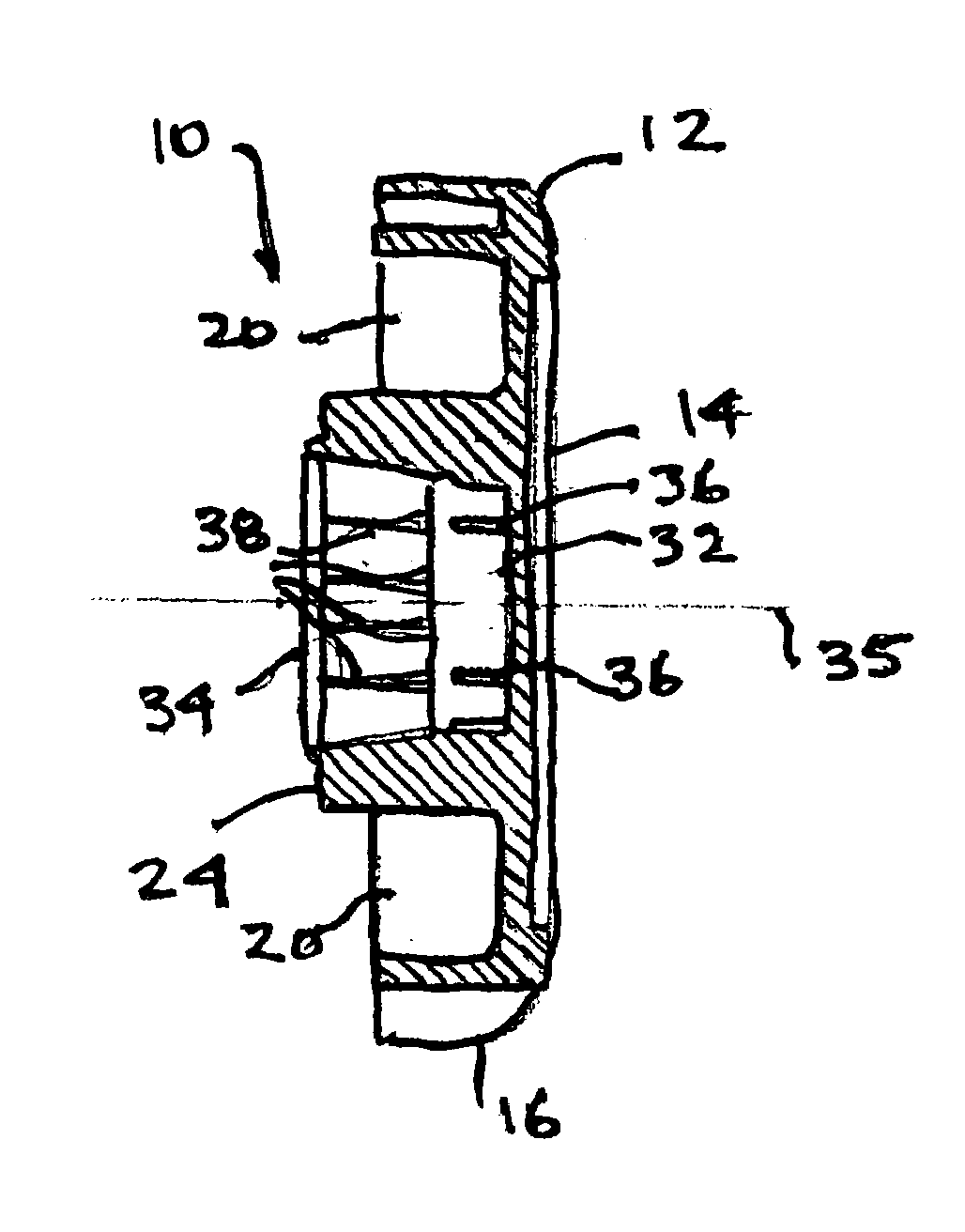
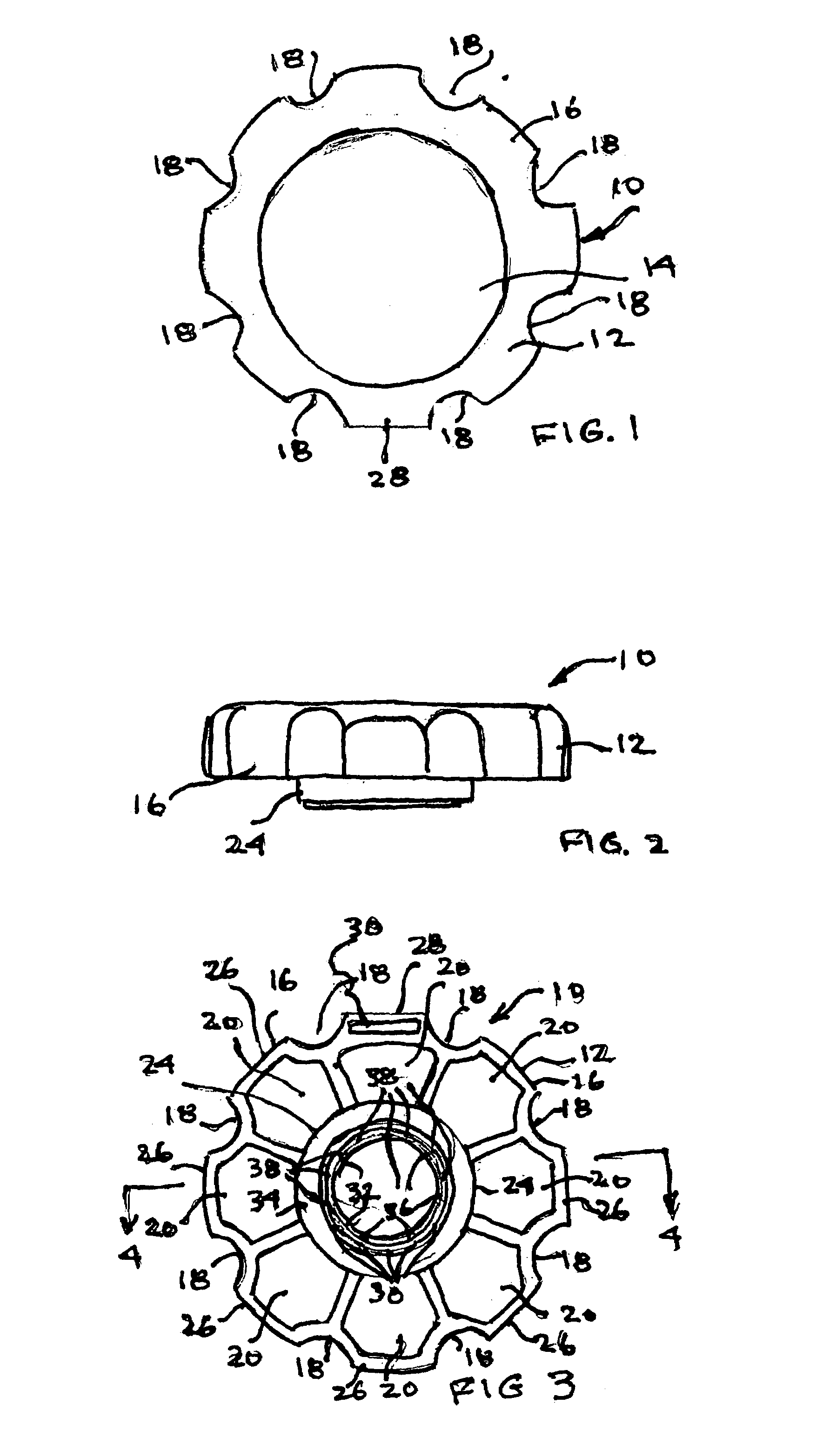
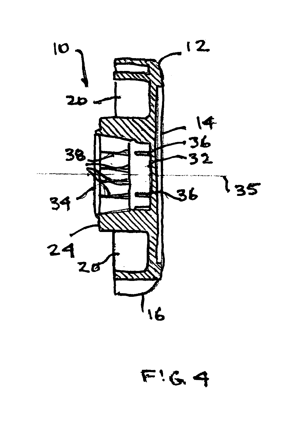
[0018]Referring to the drawings, there is shown in FIG. 1 a bottle cap remover, generally designated 10 in accordance with a presently preferred embodiment of the invention. As therein shown, the bottle cap remover 10 is a unitary integral plastic piece made, for example, by injection molding using ABS plastic. The bottle cap opener 10 comprises a circular grasping section 12, which, as shown best in FIG. 1, has the appearance of a knob. Grasping section 12 includes a central, circular section 14 that may be slightly recessed (FIG. 4) to allow a label or the like to be secured thereto. Central section 14 is surrounded by a peripheral ring 16 that includes a plurality, here shown as eight in number, of arcuate or annular recesses 18, any five of which at a given time may receive the user's fingers when the bottle cap opener 10 is used as described in greater detail below.

[0019]Cutouts or hollowed-out portions 20e may be formed in the undersides of central section 14 and ring 16 to de...


PUM


Abstract

A bottle cap remover includes a pair of axially nested socket sections of different diameters depending axially from a larger-diameter grasping section. Each of the socket sections includes frictional gripping members along their inner walls that are adapted to frictionally engage different sizes and types of metal and plastic bottle caps, thereby to enable the user to twist off and remove the bottle caps by applying a relatively small twisting force to the grasping section.

Description

BACKGROUND OF THE INVENTION[0001]1. Field of the Invention[0002]The present invention relates generally to the removal of closures from containers, and more particularly to a bottle cap remover that is capable of removing the caps from multiple kinds of bottles with a reduced twisting force.[0003]2. Description of the Prior Art[0004]Millions of people every day remove the twist-off caps from glass and plastic bottles of varying opening diameters by applying a manual twisting force to the screw-top bottle caps, thereby to remove the bottle caps and allow the liquid contents of the bottle, typically beer, juice or soda, to be poured out. For most individuals, the removal of a screw-top bottle cap can be usually achieved with relative ease by simply grasping the cap, typically with the thumb and middle finger of one hand, and rotating the cap in the counter-clockwise direction to unscrew and thus remove the cap from the bottle. On occasion, the cap may be so tightly secured to the cont...

Claims


Application Information

Patent Timeline
Patent Type & Authority Patents(United States)
IPC IPC(8): B67B7/18B67B7/15B67B7/44
CPCB67B7/18
Inventor BURTON, JOHNBURTON, ANDREW
Owner T ASSIST
Why Eureka
Try Eureka