Method for correcting the flight path of ballistically fired spin-stabilised artillery ammunition

a technology of spin-stabilised artillery and flight path, which is applied in the direction of ammunition projectiles, weapons, projectiles, etc., can solve the problems of affecting the installation space, serious difficulties, and the receiver circuit for radar distance measurement or satellite navigation

Inactive Publication Date: 2007-09-11
DIEHL BGT DEFENCE GMBH & CO KG
View PDF8 Cites 25 Cited by
  • Summary
  • Abstract
  • Description
  • Claims
  • Application Information

AI Technical Summary

Benefits of technology

[0006]In consideration of those aspects the object of the present invention is to make the error disposition of ammunition ballistically fired over a target area overall more advantageous.

Problems solved by technology

It will be appreciated however that the installation space available in the projectile tip is required for the major part for the safety and fuse devices, and the additional installation of a receiver circuit for for example radar distance measurement or satellite navigation also already gives rise to serious difficulties.
Therefore the necessary installation space for braking surfaces which are to be retracted here and for the mechanisms for moving and holding same in opposition to the dynamic loading produced by the afflux flow pressure is scarcely adequately available.
Moreover, a point of fundamental disadvantage in regard to those previously known structures is that the directionally selective braking measure means that the trajectory can only be shortened and that therefore the degree of scatter in terms of target hit plotting can only be narrowed in one direction.

Method used


Image

  • Method for correcting the flight path of ballistically fired spin-stabilised artillery ammunition
  • Method for correcting the flight path of ballistically fired spin-stabilised artillery ammunition

Examples


Embodiment Construction

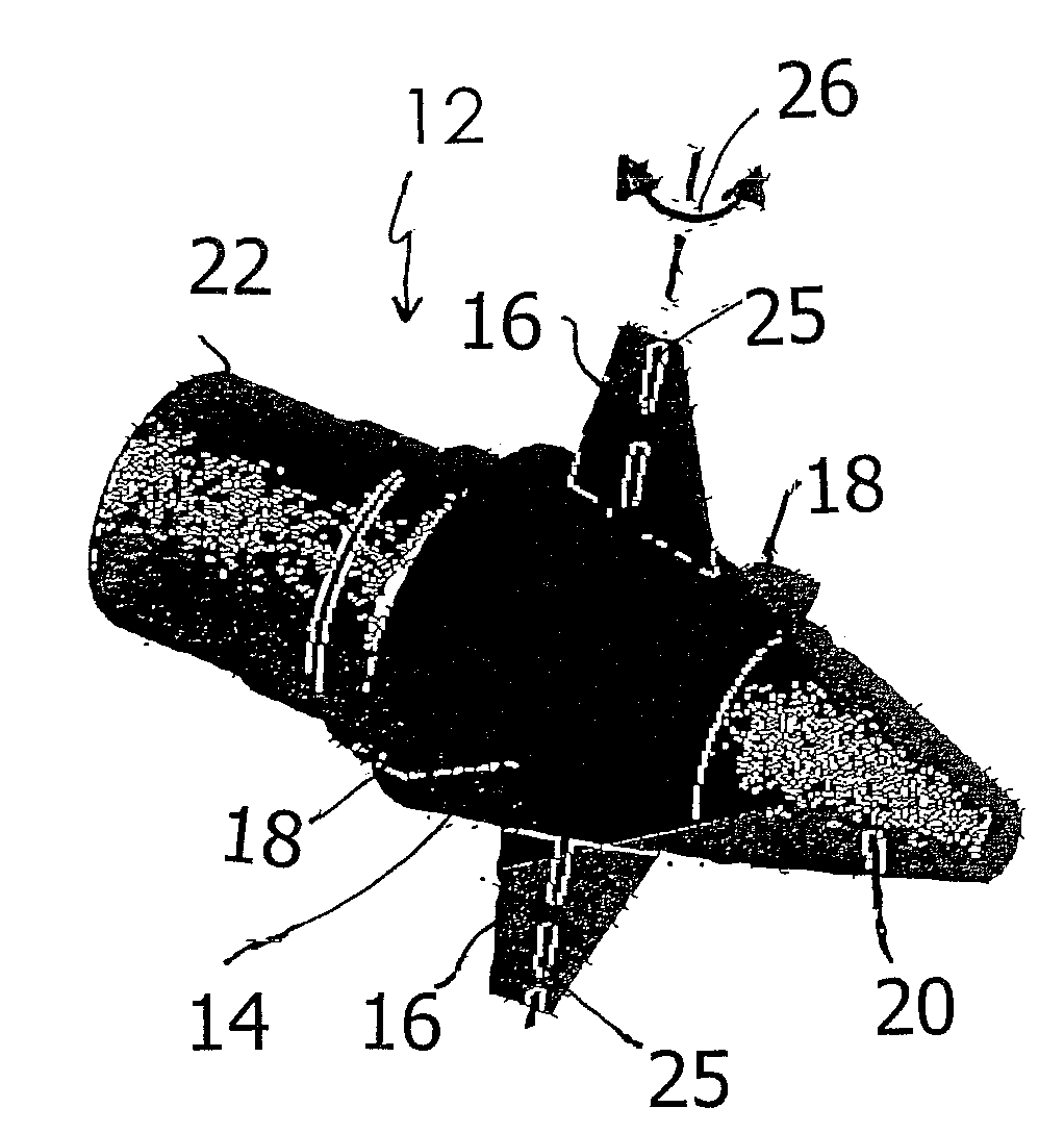
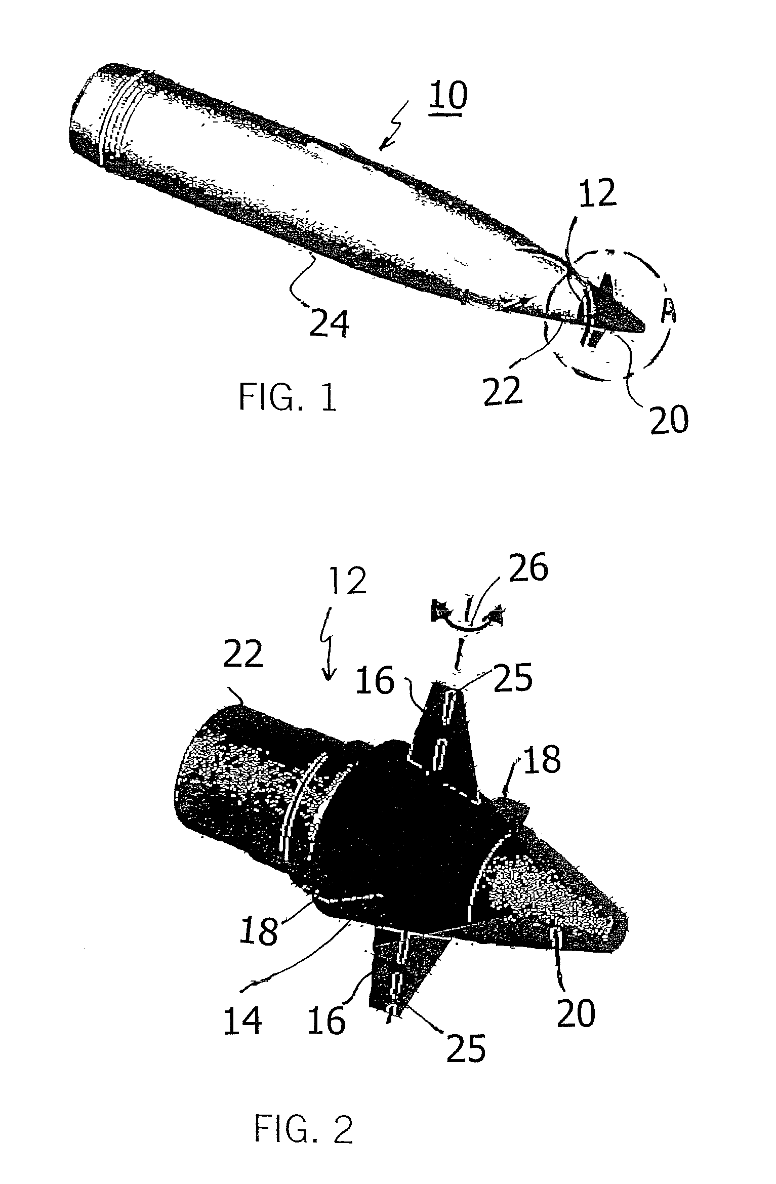
[0011]Refering now to FIG. 1, there is shown a spin-stabilized artillery pojectile 10 having an essentially cylindrical body 24. Mounted at the ogive end is a roll joint assembly 12, as illustrated in the encircled portion “A”, as represented on an enlarged scale in FIG. 2.

[0012]The roll joint assembly 12 facilitates a rotational uncoupling between the essentially slower rotating projectile fuze tip portion 20 and the more rapidly rotating or spinning projectile body 24. Hereby, the roll assambly 12 incorporates a sleedve member 14 having a pair of canard wing surfaces 16, which are each pivotable about radial control shafts 25 along the directions of the double-headed arrow 26.

[0013]Further canard surfaces 18 may be mounted on the projectile body structure. Moreover, the end strucure 22 of the arrangement 12 is insertable in the body 24 of the projectile 10.

[0014]For that purpose, mounted laterally at the tapered front part of the ammunition, more specifically in the fuse which is ...


PUM


Abstract

At very low apparatus expenditure, namely with a canard system which is adjustable in a single-axis mode, it is possible to achieve a spatially two-dimensional trajectory correction in respect of the artillery ammunition which in itself is unguided, with the additional degree of freedom in respect of trajectory extension and thus an extraordinary increase in the precision of delivery in relation to the predetermined target point.

Description

BACKGROUND OF THE INVENTION[0001]1. Field of Invention[0002]The invention concerns a method of trajectory correction, which is effected in dependence on the instantaneous roll position in space, in respect of ballistically launched spin-stabilised artillery ammunition by means of canard surfaces, which are oriented radially in a single-axis configuration at the fuse tip, which is tapered in relation to the ammunition body thereof and which is roll decoupled.[0003]2. Discussion of the Prior Art[0004]A method of this type is known from DE 198 45 611 A1. There, the fuse tip which can be screwed on to the ammunition body has a component which, for spin reduction purposes, is rotatable with respect to the spin-stabilised ammunition body and from which two braking surfaces which are held rigidly at the same angle of incidence can be extended in the manner of canard wings transversely with respect to the spin axis in order to exert a directed braking action on the current trajectory of the...

Claims


Application Information

Patent Timeline
Patent Type & Authority Patents(United States)
IPC IPC(8): F42B10/04F42B10/64
CPCF42B10/64
Inventor LEININGER, JURGEN
Owner DIEHL BGT DEFENCE GMBH & CO KG
Why Eureka
Try Eureka