
Retaining member

a technology of retaining member and body, which is applied in the direction of machine supports, domestic objects, applications, etc., can solve the problems of vibration in the audible range, the brake line on the body-in-white,

Active Publication Date: 2007-09-11
ITW AUTOMOTIVE PRODS
View PDF32 Cites 50 Cited by
  • Summary
  • Abstract
  • Description
  • Claims
  • Application Information

AI Technical Summary

Benefits of technology

[0006]Accordingly, it is the object of the invention to provide a retaining element of a plastic which enables the pressure surges transmitted via the lines to be isolated better from the support.
[0010]When the inventive retaining member is mounted on a support the resilient contact are will spring in more or less. On the side of the retaining member that faces the support, the contact between the retaining member and the support is concentrated onto the contact area. As distinguished from the basic body, the contact area is designed as being resilient or more intensely resilient. Hence, the contact area exhibits a lower spring constant than does the basic body. Retaining members having a virtually rigid basic body are also incorporated. The resilient contact area significantly reduces the transmission of pressure surges onto the support. Moreover, the contact area maintains the retaining area at a distance from the support. The reduction of pressure surges is favoured by the relatively low spring constant of the contact area. Summarizing, the inventive retaining member considerably improves the acoustic isolation of the lines from the support.
[0023]In an aspect, the line seating is formed in a substantially cylindrical, elastically expandable cup having an insertion slot. The cup is a clamping member into which the line can be snapped simply through the insertion slot. In an aspect, at least some part of the line seating has a lining made of a non-rigid plastic material. This helps achieve a further improvement to the acoustic isolation of the line from the support.
[0025]In an aspect, the contact area and / or the linings is / are manufactured from a thermoplastic elastomer. Thermoplastic elastomers allow for a low spring constant of the contact area and / or linings (low friction / low surface load of the contact areas (in case of compressed constructional space).

Problems solved by technology

For example, this problem occurs in mounting brake lines on the body-in-white sheets of motor vehicles.
Here, the transmission of pressure surges can cause vibrations in the audible range which can even be intensified by resonant bodies existing in the motor vehicle.

Method used


Image

  • Retaining member
  • Retaining member
  • Retaining member

Examples


Embodiment Construction

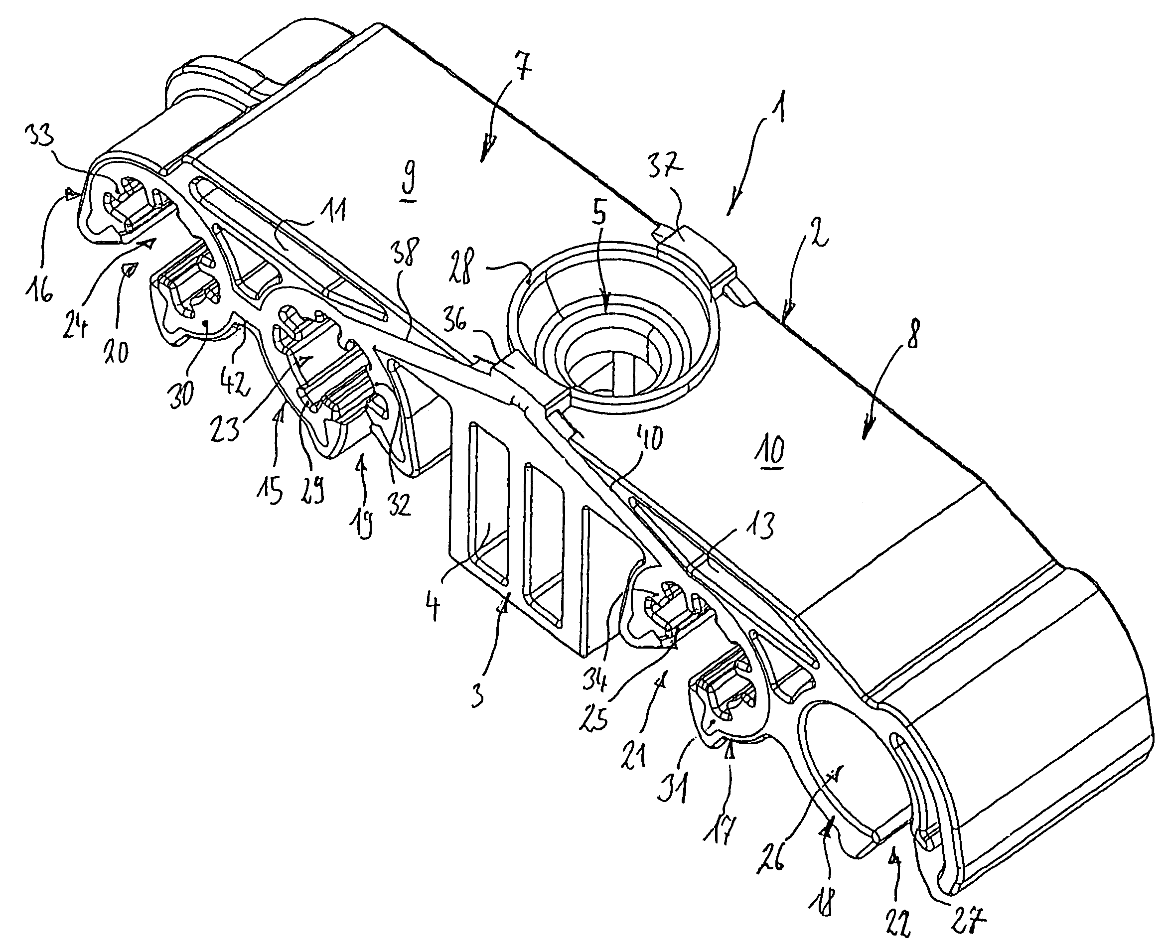
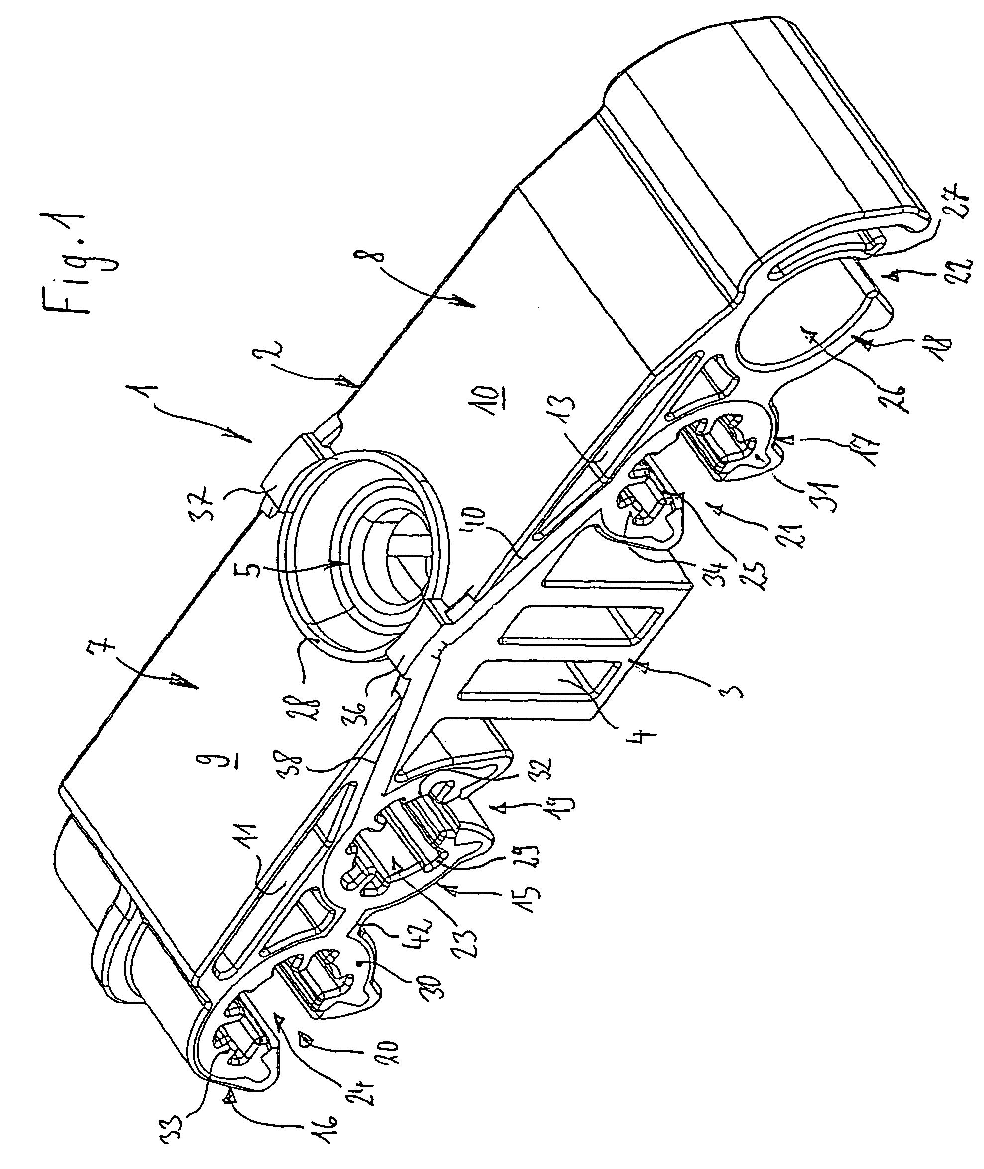
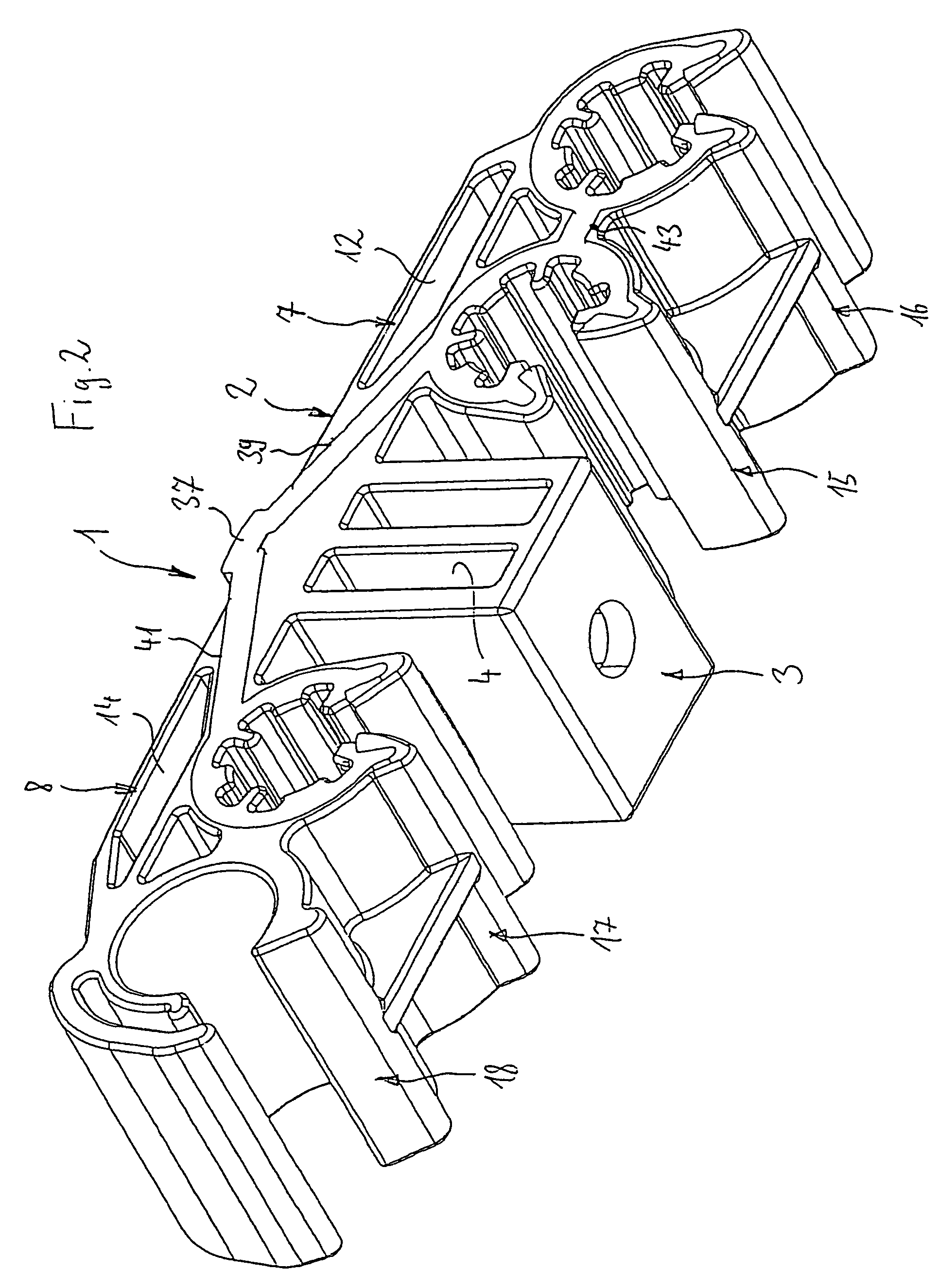
[0032]The inventive retaining member 1 has a basic body 2 of a rigid plastic material. For example, this is a PA (e.g. PA 6.6 or PA 6).

[0033]The basic body 2 comprises a central mounting area 3 which is formed in a box shape or cage shape. A seating 4 for mounting bolt is located in the mounting area 3. The seating 4 is accessible through a hole 5 in that side of the mounting area 3 which faces the support. The seating 4 has disposed therein two groups of parallel lamellae 6 which are on two opposed sides and are inclined towards the hole 5 on either side.

[0034]Retaining areas 7, 8 extend away from two opposed sides of the mounting area 3. The areas comprise an approximately plate-shaped retaining arm 9, 10 each which, starting from the two narrow sides, exhibit pocket-shaped cavities 11, 12, 13, 14. The retaining arms 9, 10 extend from the level of that side of of the mounting area 3 which is to be placed against the support.

[0035]The arms each carry two two clamping members 15 to ...


PUM


Abstract

A retaining member in plastic, suited for retaining at least one line on a support, includes a basic body with a mounting area for mounting on the support and retaining area projecting from at least one side of the mounting area with at least one line seating for at least one line, and a resilient contact area projecting from the side of the mounting area that requires to be placed on the support.

Description

FIELD OF THE INVENTION[0001]The invention relates to a retaining member of a plastic material which is useful for holding lines on a support.BACKGROUND OF THE INVENTION[0002]When pipes, flexible tubes, and other lines through which pressure pulses are transmitted are mounted on a support by means of retaining members it is desirable to isolate the pressure pulses from the support. For example, this problem occurs in mounting brake lines on the body-in-white sheets of motor vehicles. Here, the transmission of pressure surges can cause vibrations in the audible range which can even be intensified by resonant bodies existing in the motor vehicle. Avoiding the transmission of the pressure surges onto the support from the lines is also called “acoustic isolation” in this application.[0003]DE 40 34 545 A1 has made known a two-piece retaining member of a plastic for holding at least one tubular component that has an outer cup of a hard material mountable on a support via a retaining area a...

Claims


Application Information

Patent Timeline
Patent Type & Authority Patents(United States)
IPC IPC(8): F16L3/08F16F15/02F16L3/223F16L3/12
CPCF16L3/223F16L55/035
Inventor BAUER, CHRISTIAN
Owner ITW AUTOMOTIVE PRODS
Learn More