Tube joint for fuel tank

a fuel tank and tube joint technology, applied in the direction of hose connection, non-disconnectible pipe joint, transportation and packaging, etc., can solve the problems of difficult to meet the joint strength, poor adhesion properties of gasoline barrier materials, and relatively poor fuel impermeability of synthetic resins such as hdpe, so as to prevent the fuel from permeating and improve the fuel impermeability

Active Publication Date: 2007-09-11
HONDA MOTOR CO LTD
View PDF4 Cites 13 Cited by
  • Summary
  • Abstract
  • Description
  • Claims
  • Application Information

AI Technical Summary

Benefits of technology

[0012]According to this tube joint, the seal groove is formed between the projecting portion of the extension portion and the joint body, so that a fluid-tight seal can be obtained between the joint body and the tube fitted onto the joint body. A fluid-tight seal can be obtained also at the contact surface between the extension portion and the joint body. Further, the nail portion provided at or adjacent to the distal end of the barrier layer that is formed of a material with a sufficient hardness can bite into the inner peripheral surface of the tube so as to prevent the tube from being pulled out from the tube joint. According to the present invention, since the joint body is weldable to the tank body, a firm welding can be obtained between the tube joint and the tank body. Further, since the barrier layer is formed of a material which excels in fuel impermeability, it is possible to prevent the fuel from permeating the tube joint.

Problems solved by technology

However, synthetic resin such as HDPE is relatively poor in fuel impermeability.
However, these gasoline barrier materials are poor in adhesion properties upon heat welding and difficult to satisfy the joint strength between the tank body and the tube joint.
However, it is very difficult to produce this tube joint by a single material.
Further, if a sufficient adhesion is not obtained between the different kinds of resin materials, the adhered surfaces may be peeled, leading to the entry of water droplets into the tank body 100.

Method used


Image

  • Tube joint for fuel tank
  • Tube joint for fuel tank
  • Tube joint for fuel tank

Examples


Embodiment Construction

[0018]With reference to the accompanying drawings, one preferred embodiment of the present invention will be described below.

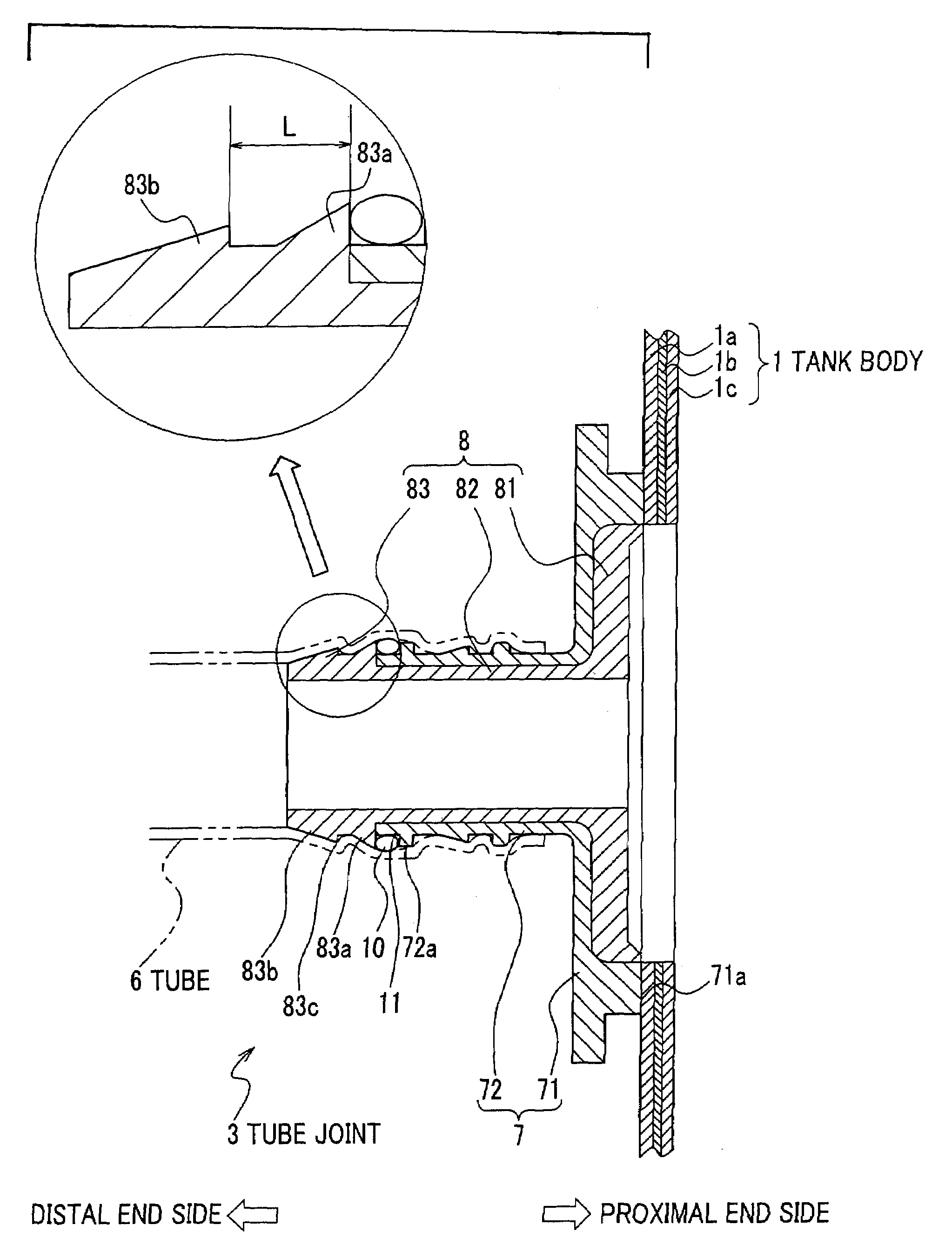
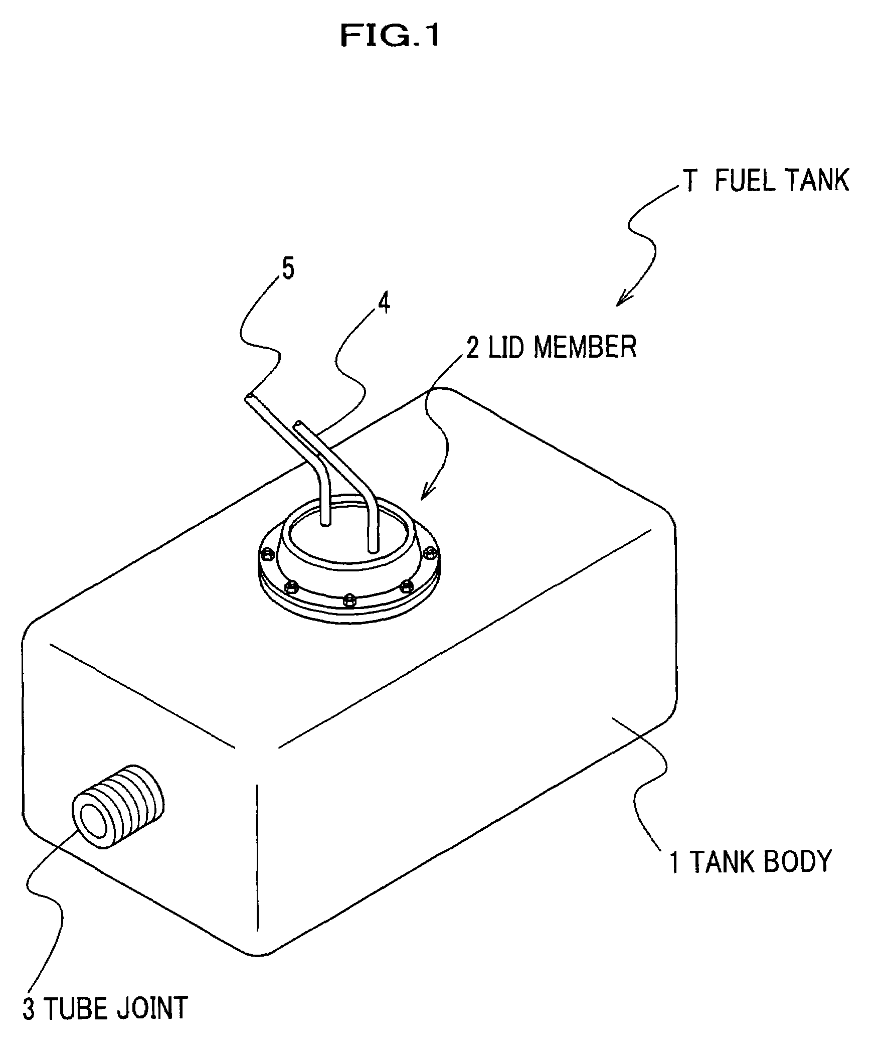
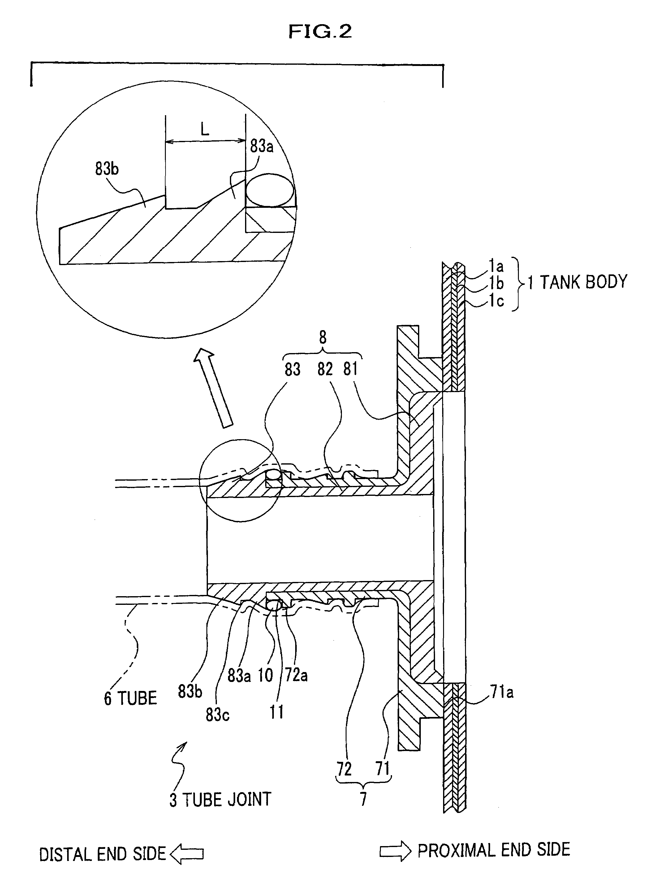
[0019]As shown in FIG. 1, a fuel tank T made of resin includes a resin tank body 1 for storing fuel, a lid member 2 for covering an opening of the tank body 1, and a tube joint 3 for connecting a tube 6 (see FIG. 2) that is further connected to an oil filler port of the vehicle body. In this embodiment, one end of the tube joint 3 which is attached to the tank body 1 is referred to as a proximal end, and the other end of the tube joint 3 is referred to as a distal end.

[0020]As shown in FIG. 1, a fuel supply passage 4 and a return passage 5 are integrally attached to the lid member 2. The fuel supply passage 4 is for supplying fuel from a fuel pump (not shown) arranged within the tank body 1 to an engine of the vehicle, and a return passage 5 is for recycling excess fuel from the engine.

[0021]As seen in FIG. 2, the tank body 1 is formed by blow molding and has ...


PUM

PropertyMeasurementUnit
hardnessaaaaaaaaaa
areaaaaaaaaaaa
diameteraaaaaaaaaa

Abstract

A tube joint for a fuel tank includes a joint body having a tubular shape, and a barrier layer covering the inner surface of the joint body. The joint body is formed of a material which is weldable to a tank body, and the barrier layer is formed of a material which has fuel impermeability and a predetermined hardness. The barrier layer has an extension portion extending from a distal end of the joint body along an axial direction of the joint body. The extension portion includes a projecting portion which protrudes radially and outwardly of the extension portion at or adjacent to a proximal end of the extension portion such that a seal groove is formed between the projecting portion and the joint body, and a nail portion which protrudes radially and outwardly of the extension portion at or adjacent to a distal end of the extension portion.

Description

BACKGROUND OF THE INVENTION[0001]The present invention generally relates to a tube joint for fuel tanks made of resin materials.[0002]In recent years, plastic containers produced by blow molding have been used as a fuel tank of vehicles as they excel in rust preventative characteristics and weight reduction as well as their high productivity.[0003]Various parts are attached to the tank body of the fuel tank through a tube joint. These parts include, for example, a vent valve, a check valve, and a fuel pump. The vent valve retains the internal pressure of the tank body at a certain level by discharging fuel evaporation gas that is held in a space above the oil level from the tank.[0004]In the case where the tank body and the tube joint are both produced by the same kind of synthetic resin, such as high density polyethylene (hereinafter referred to as “HDPE”), they can be jointed by heat welding. This can simplify the manufacturing process of the fuel tank.[0005]Since effusion of the ...

Claims


Application Information

Patent Timeline
Patent Type & Authority Patents(United States)
IPC IPC(8): F16L25/00B60K15/03B60K15/01B60K15/04F16L33/24F16L41/08F16L47/02F16L47/26F16L47/32F16T1/00
CPCF16L47/02F16L47/26F16L47/32B60K15/03B60K15/03177B60K2015/03493B60K2015/03453B60K2015/0477B60K2015/03065
Inventor ISAYAMA, AKIRAMATSUMOTO, HIDEKI
Owner HONDA MOTOR CO LTD
Why Eureka
Try Eureka