Fuel cell system

a fuel cell and system technology, applied in the field of fuel cell systems, can solve the problems of odorant deteriorating the output characteristics of the fuel cell, and the leakage of hydrogen gas can be sensed, so as to reduce the effect of reducing the concentration of hydrogen gas contained

Inactive Publication Date: 2007-09-11
TOYOTA JIDOSHA KK
View PDF6 Cites 8 Cited by
  • Summary
  • Abstract
  • Description
  • Claims
  • Application Information

AI Technical Summary

Benefits of technology

[0011]In the first aspect, the odorant may be a specific odorant that is unlikely to deteriorate output characteristics of the fuel cell. For example, the odorant may be butyric acid. In this construction, it is possible to inhibit output characteristics of the fuel cell from deteriorating due to the odorant. Therefore, it is possible to enhance a degree of freedom in disposing the odorant removal portion.
[0013]In the aforementioned aspect, the odorant removal portion may be provided in a confluent off gas passage into which the fuel off gas passage and the oxidative off gas passage converge. In this construction, it is also possible to sense leakage of hydrogen from the fuel off gas passage. Because the fuel off gas is mixed with the oxidative off gas, the concentration of hydrogen gas contained in the discharged gas can be reduced. Furthermore, in the case where the odorant enters the oxidative off gas passage via the fuel cell, it is also possible to remove the odorant that has entered the oxidative off gas.
[0014]Alternatively, in the aforementioned first aspect, the fuel off gas passage may be designed to be connected to the oxidative gas passage, and the odorant removal portion may be provided downstream of a connecting point between the fuel off gas passage and the oxidative gas passage. In this construction, it is also possible to sense leakage of hydrogen gas from the fuel off gas passage. Because the fuel off gas is mixed with the oxidative gas, it is also possible to reduce a concentration of hydrogen gas contained in the discharged gas.

Problems solved by technology

However, the odorant often deteriorates output characteristics of the fuel cell.
In such a fuel cell system, however, leakage of hydrogen gas can be sensed only in a fuel gas passage region upstream of a fuel cell.

Method used


Image

  • Fuel cell system
  • Fuel cell system
  • Fuel cell system

Examples


first embodiment

A. First Embodiment

A-1. Overall Construction of Fuel Cell System

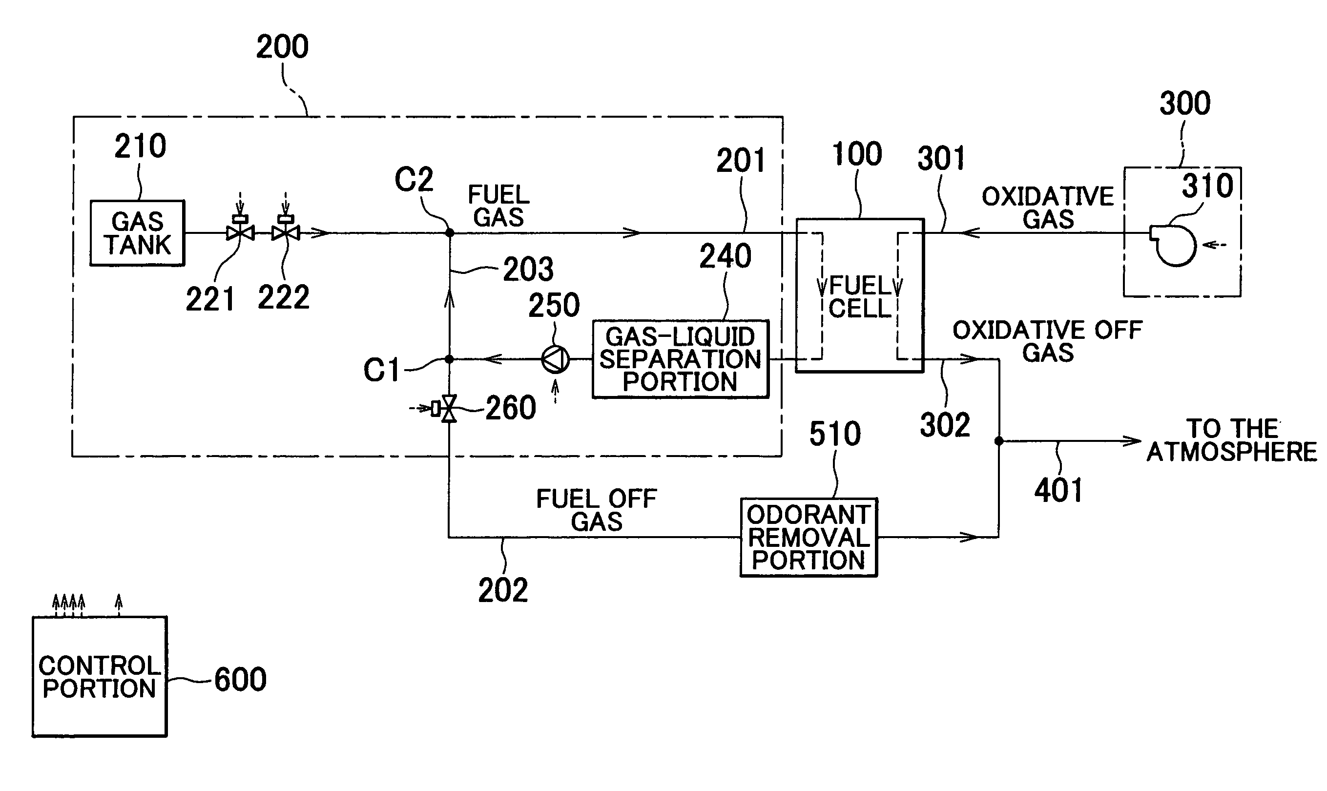
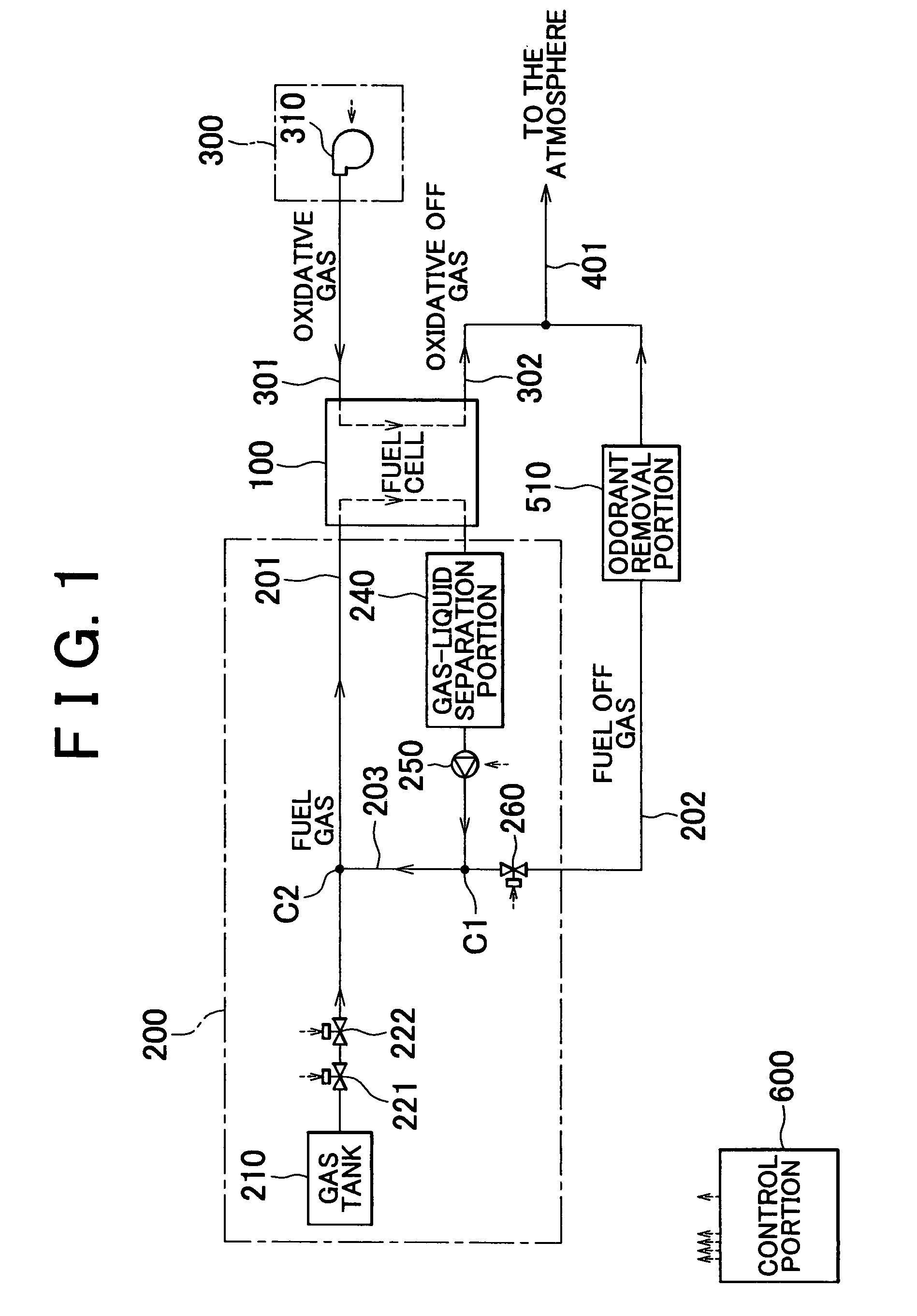
[0035]Next, modes of implementing the invention will be described on the basis of embodiments thereof. FIG. 1 is an explanatory view showing an overall construction of a fuel cell system in accordance with the first embodiment. This fuel cell system is installed in a vehicle.

[0036]As shown in FIG. 1, a fuel cell system includes a fuel cell 100, a fuel gas supply portion 200 for supplying the fuel cell with a fuel gas containing hydrogen gas, an oxidative gas supply portion 300 for supplying the fuel cell with an oxidative gas (air) containing oxygen gas, and a control portion 600 for controlling operation of the entire fuel cell system. A fuel gas passage 201 through which a fuel gas supplied from the fuel gas supply portion 200 flows and a fuel off gas passage 202 through which a spent fuel off gas flows are connected to the fuel cell 100. Further, an oxidative gas passage 301 through which an oxidative gas supplied fr...

second embodiment

B. Second Embodiment

[0057]FIG. 5 is an explanatory view showing an overall construction of a fuel cell system in accordance with the second embodiment. Although FIG. 5 is substantially identical with FIG. 1, disposal of the odorant removal portion 520 has been modified. To be more specific, although the odorant removal portion 510 is provided in the fuel off gas passage 202 downstream of the shut-off valve 260 in FIG. 1, the odorant removal portion 520 is provided in the fuel off gas passage 202 between the circulating pump 250 and the first connecting point C1 in FIG. 5.

[0058]Even in the case where the construction shown in FIG. 5 is adopted, it is possible to sense leakage of hydrogen gas from the fuel gas passage 201, leakage of hydrogen gas from the fuel cell 100, and leakage of hydrogen gas from the fuel off gas passage at a portion upstream of the odorant removal portion 520.

[0059]In the case where the fuel off gas discharged from the fuel cell 100 is caused to circulate from ...

third embodiment

C. Third Embodiment

[0062]FIG. 7 is an explanatory view showing an overall construction of a fuel cell system in accordance with the third embodiment. Although FIG. 7 is substantially identical with FIG. 1, the confluent off gas passage 401 is omitted, and an air blower 290 is added. The air blower 290 is connected to the fuel off gas passage 202 at a third connecting point C3 downstream of the shut-off valve 260, and introduces air into the fuel off gas passage 202. The air that has been introduced into the fuel off gas passage 202 is supplied to an odorant removal portion 530.

[0063]Even in the case where the construction shown in FIG. 7 is adopted, the concentration (volume percentage) of hydrogen gas contained in the fuel off gas discharged to the atmosphere can be reduced by means of air supplied from the air blower 290.

C-1. First Modification Example of Third Embodiment

[0064]FIG. 8 is an explanatory view showing an overall construction of a fuel cell system in accordance with a ...


PUM

PropertyMeasurementUnit
temperatureaaaaaaaaaa
degree of freedomaaaaaaaaaa
concentrationaaaaaaaaaa

Abstract

A fuel cell system comprises a fuel cell, a fuel gas passage through which a fuel gas containing an odorant and hydrogen gas supplied to the fuel cell flows, an oxidative gas passage through which an oxidative gas supplied to the fuel cell flows, a fuel off gas passage through which a fuel off gas discharged from the fuel cell flows, an oxidative off gas passage through which an oxidative off gas discharged from the fuel cell flows, and an odorant removal portion provided in the fuel off gas passage. The odorant removal portion removes the odorant after the fuel gas has been introduced into the fuel cell.

Description

INCORPORATION BY REFERENCE[0001]The disclosure of Japanese Patent Application No. 2002-298505 filed on Oct. 11, 2002, including the specification, drawings, and abstract is incorporated herein by reference in its entirety.BACKGROUND OF THE INVENTION[0002]1. Field of the Invention[0003]The invention relates to a fuel cell system and, more particularly, to an art for removing an odorant from a mixed gas containing hydrogen gas and the odorant.[0004]2. Description of the Related Art[0005]A fuel cell generates electricity by means of hydrogen gas contained in a fuel gas and oxygen gas contained in an oxidative gas. A spent fuel gas (fuel off gas) and a spent oxidative gas (oxidative off gas) are discharged from the fuel cell.[0006]In a fuel cell system, a mixed gas (fuel gas) containing hydrogen gas and an odorant is used to sense leakage of hydrogen gas at an early stage. However, the odorant often deteriorates output characteristics of the fuel cell. Hence, there has been devised a co...

Claims


Application Information

Patent Timeline
Patent Type & Authority Patents(United States)
IPC IPC(8): H01M8/02H01M8/04H01M8/24H01M8/06
CPCH01M8/04089Y02E60/50
Inventor MIURA, SHIMPEIMURATA, SHIGEAKI
Owner TOYOTA JIDOSHA KK
Why Eureka
Try Eureka