

Fuel cell system
a fuel cell and system technology, applied in the field of fuel cell systems, can solve the problems of odorant deterioration of the output characteristics of the fuel cell, space for providing the odorant removal portion needs not be prepared, and leakage of hydrogen gas can be sensed
- Summary
- Abstract
- Description
- Claims
- Application Information
AI Technical Summary
Benefits of technology
Problems solved by technology
Method used
Image

Examples
third embodiment
[0064] FIG. 8 is an explanatory view showing an overall construction of a fuel cell system in accordance with a first modification example of the Although FIG. 8 is substantially identical with FIG. 7, disposal of the odorant removal portion 530A has been modified. More specifically, although the odorant removal portion 530 is provided in the fuel off gas passage 202 in FIG. 7, an odorant removal portion 530A is provided inside a fuel cell 100C in FIG. 8. In FIG. 8, the fuel off gas passage 202 is connected to the oxidative gas passage 301, and the air blower 290 is omitted.
[0065] FIG. 9 is an explanatory view schematically showing an internal construction of the fuel cell shown in FIG. 8. As shown in FIG. 9, the fuel cell 100C includes three stacks 101 to 103, a plurality of first branch pipes 131 for distributing an oxidative gas to the stacks respectively, and a plurality of second branch pipes 132 for gathering oxidative off gases flowing from the stacks respectively. As descri...
third modification example
C-3. Third Modification Example of Third Embodiment
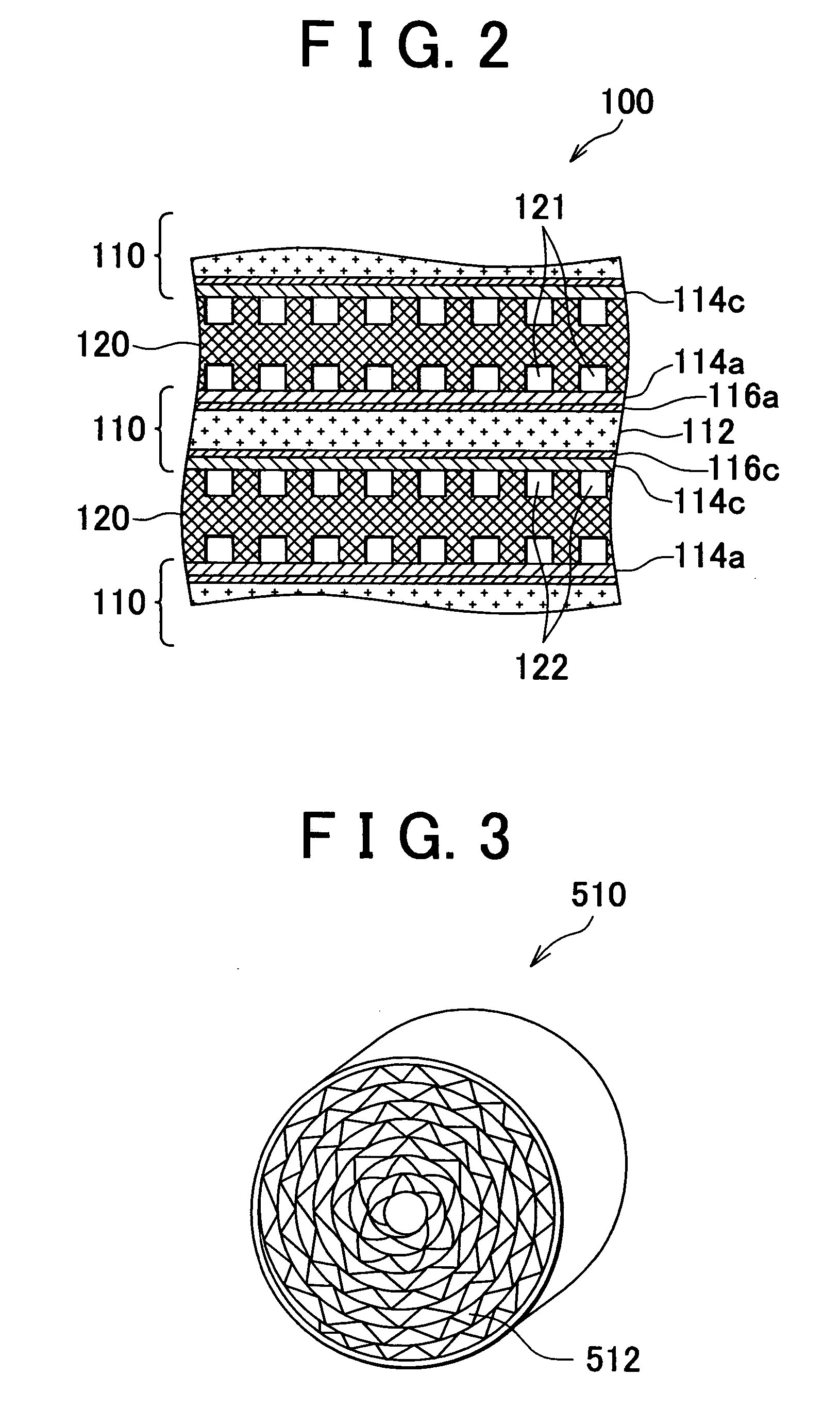
[0070] In the case where the odorant removal portions 530 and 530A are supplied with air (oxygen gas) as shown in FIGS. 7 and 8, they may include a catalyst for promoting oxidation of an odorant instead of a porous adsorbent. As the catalyst, a noble metal catalyst such as Pt, Pd, Ru or the like can be used. This odorant removal portion can be prepared, for example, by soaking the carrier 512 shown in FIG. 3 in a solution containing the catalyst and then baking the carrier 512.
[0071] This odorant removal portion can oxidize (burn) the odorant contained in the fuel off gas by means of oxygen gas contained in supplied air. That is, even in the case where this odorant removal portion is adopted, the odorant can be removed from the fuel off gas, and replacement of the odorant treatment portion can be omitted.
[0072] As described with reference to FIG. 2, the catalyst 116c containing a noble metal such as Pt or the like is formed in the i...
fourth embodiment
D. Fourth Embodiment
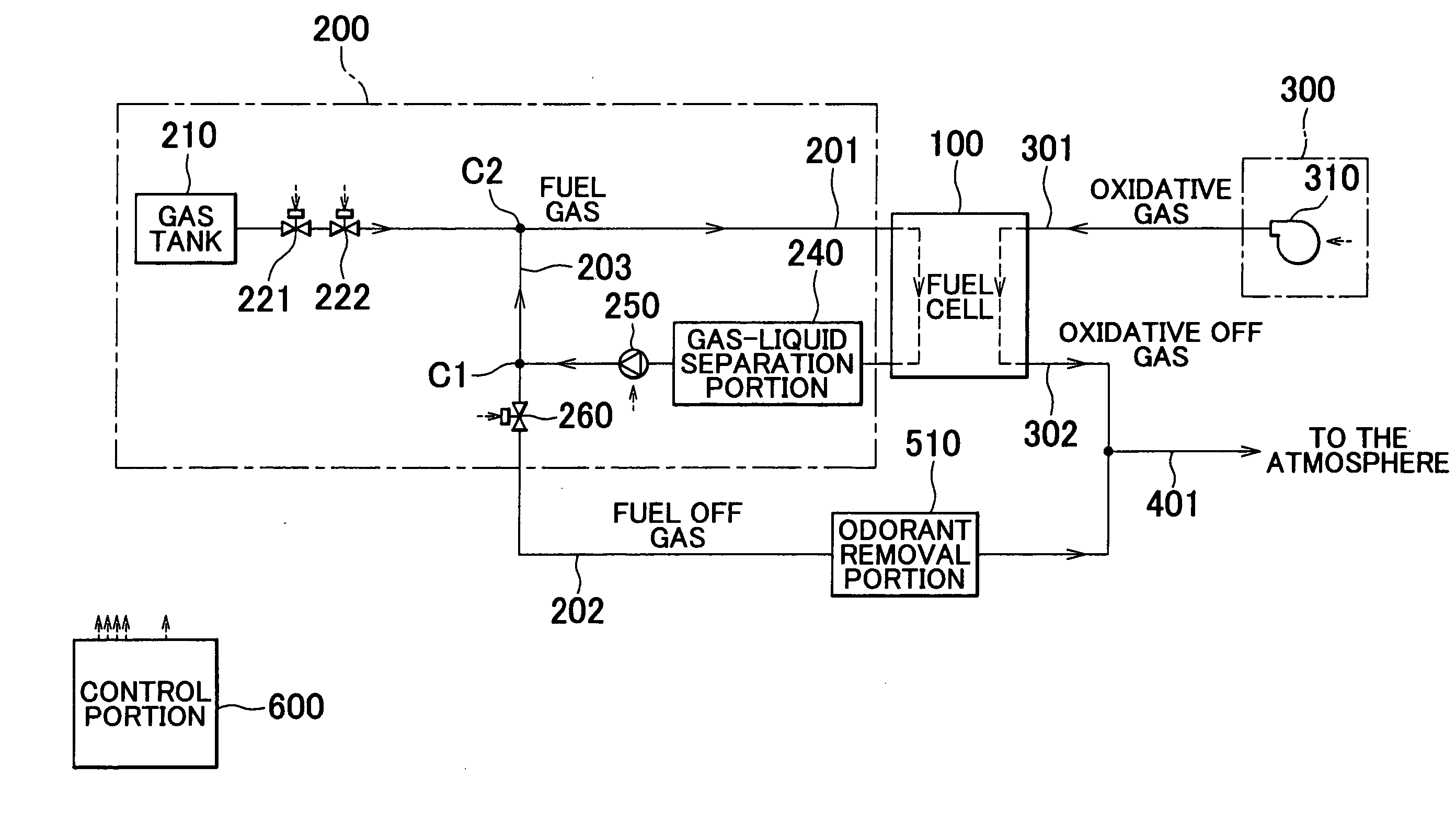
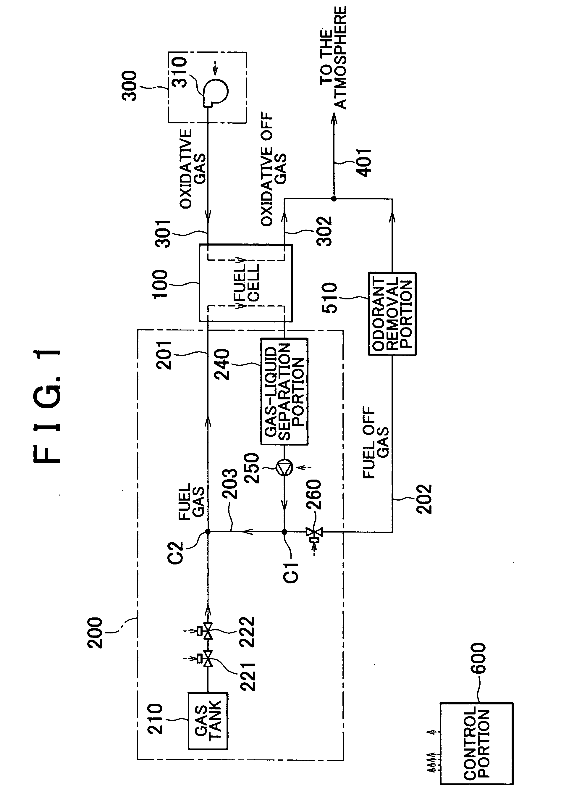
[0073] FIG. 10 is an explanatory view showing an overall construction of a fuel cell system in accordance with the fourth embodiment. Although FIG. 10 is substantially identical with FIG. 1, disposal of the odorant removal portion 540 has been modified. More specifically, although the odorant removal portion 510 is provided in the fuel off gas passage 202 in FIG. 1, the odorant removal portion 540 is provided in the confluent off gas passage 401 in FIG. 10.
[0074] If the construction shown in FIG. 10 in which the odorant removal portion 540 is provided in the confluent off gas passage 401 is adopted, it is possible to sense leakage of hydrogen gas from the fuel gas passage 201, leakage of hydrogen gas from the fuel cell 100, and leakage of hydrogen gas from the fuel off gas passage 202. Further, since the fuel off gas is mixed with the oxidative off gas, it is also possible to reduce a concentration (volume percentage) of hydrogen gas contained in the mixed off ga...
PUM
 Abstract
Description
Claims
Application Information